This article is reprinted from the Jishu Community.
Jishu Column:SiRider S1 Chip Development Board Information
Hello everyone, this review focuses on a domestic chip (Dragon Eagle No. 1 siengine SE1000).
The main focus is on its AI capabilities, written around the theme of “how to run a complete AI application on a development board.” Initially, we will compile a simple app based on the information provided by the official source to familiarize ourselves with the process, understand how to configure the development environment, what tools are needed, and what the operational workflow is. Later, we will run a more complex AI model, explain the function of each module in the software SDK (parser, quant, Gbuilder, simulator, profiler), go through the code step by step, and discuss how to DIY to adapt to your own needs, so let’s go!
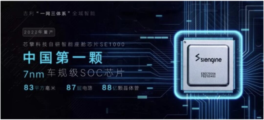
The Dragon Eagle No. 1 is a domestic 7nm intelligent cockpit chip, equipped with an 8-core CPU and a 14-core GPU. The CPU computing power can reach 90-100K DMIPS, the GPU computing power is over 900 GFLOPS, and the NPU computing power reaches 8 TOPS, comparable to Qualcomm’s 8155. According to AnTuTu benchmark scores, the data is indeed similar. It is currently known to be mounted in the Geely Auto’s Lynk & Co 08 (released in September 2023).
Positioned as a cockpit chip, the “Dragon Eagle No. 1” will not only be responsible for the computation and display of the central control screen but also for the display of the car’s instrument panel, functional screens, and even HUD. The “Dragon Eagle No. 1” supports input from 11 camera data streams (unfortunately, as of now, I am still unable to purchase compatible cameras for application development) and can support up to 7 high-definition displays.
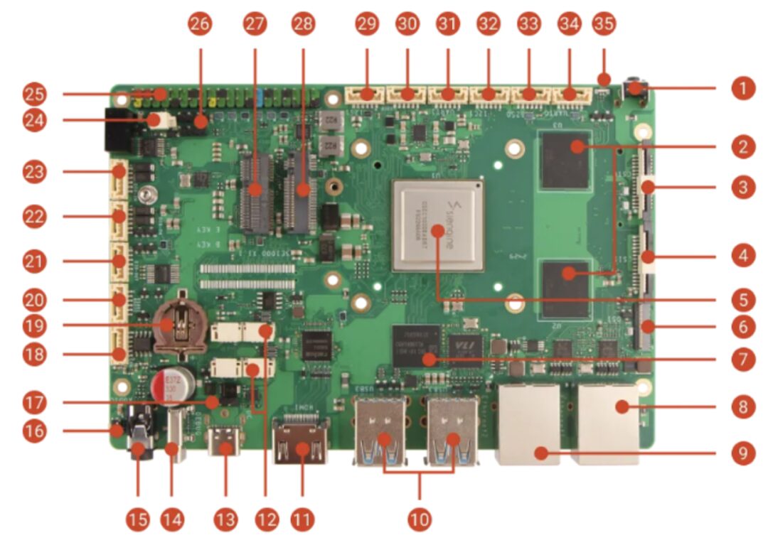
The “Dragon Eagle No. 1” will run three operating systems simultaneously: RTOS for the instrument panel, Linux for the HUD, and Android for the central control screen (the SDK currently provided defaults to using the Linux system); the development board is designed by a third party, RADXA, and the model is SiRider S1. The specific link is here: https://docs.radxa.com/sirider/s1
Although the automotive-grade materials in the BOM have been replaced with ordinary materials, its solid configuration (16GB LPDDR5, 128G UFS) still brings the cost to over a thousand yuan, which is more expensive than similar development boards (RK3588, Raspberry Pi) by three to five hundred yuan, which is actually reasonable, as RK3588 has a 4-core A76, 6 TOPS NPU, and 450 GOPS, which are slightly weaker than SiRider S1.
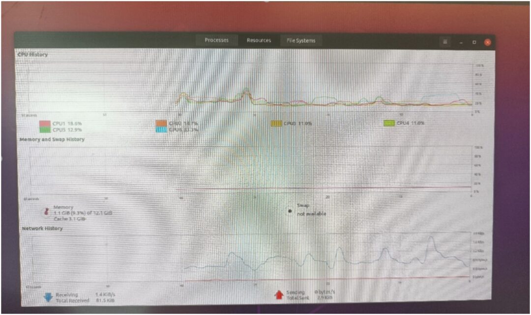
Since we are focusing on the AI part, we will not go into detail about the firmware compilation, as the board comes pre-loaded with Ubuntu firmware. After unboxing, just plug in an HDMI monitor, and connect the mouse and keyboard to get started!
As you can see, Ubuntu allocated 4 big cores A76 + two small cores A55; the content used 12GB, and the rest is allocated to FreeRTOS.
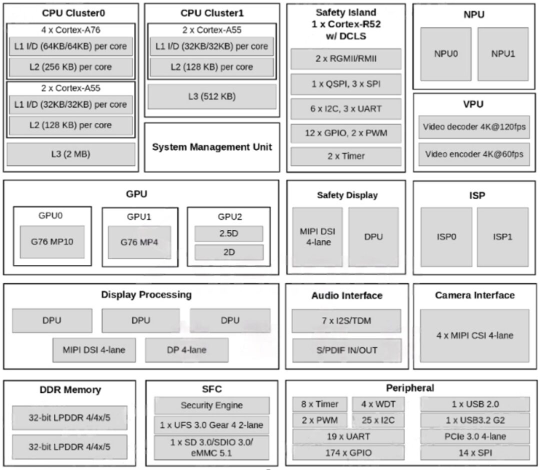
As shown in the SOC framework diagram below, the main computing power and video encoding/decoding parts are quite impressive, suitable for applications like NAS, soft routing, tablets, TV boxes, etc. The peripheral part is similarly abundant, with the most interfaces being UART, IIC, and SPI, which are all low-speed general-purpose interfaces. Therefore, if you want to develop applications related to peripheral control, it is not directly about fast control (for example, FOC brushless motors generally require 3 PWM interfaces/motors for control, but only 2 are provided here), but rather through low-speed interfaces to indirectly drive peripheral modules, such as opening doors, trunks, wipers, etc., which do not have high real-time requirements. Thus, we should try to choose well-packaged independent modules for these three types of interfaces (UART/IIC/SPI) when developing applications.
2. AI Knowledge Introduction
Alright, with the background introduction complete, let’s now dive into the AI content! In this era of diverse large models, I believe everyone has some understanding of AI!
“AI is artificial intelligence!”
“AI can talk to you like a person!”
“AI can turn your verbal descriptions into actual images!”
In fact, besides these impressive forms of AI, the time clocking devices (essential for workers), facial recognition machines, surveillance cameras, microphones, etc. all contain AI technology. You must be curious:
How does AI run on specific hardware devices?
If I have an idea that I want to implement on specific hardware rather than a general PC, what should I do?
Next, I will answer these questions one by one.
Similar to the question of how to fit an elephant into a refrigerator, the top-level process of creating an AI application is as follows:
Step one, you need to have a genius-like or foolish idea, and propose requirements for this idea;
Step two, based on the requirements, train a model;
Step three, deploy the model onto specific hardware.
The first and second steps are not the main focus of our learning this time, so we will just briefly cover them.
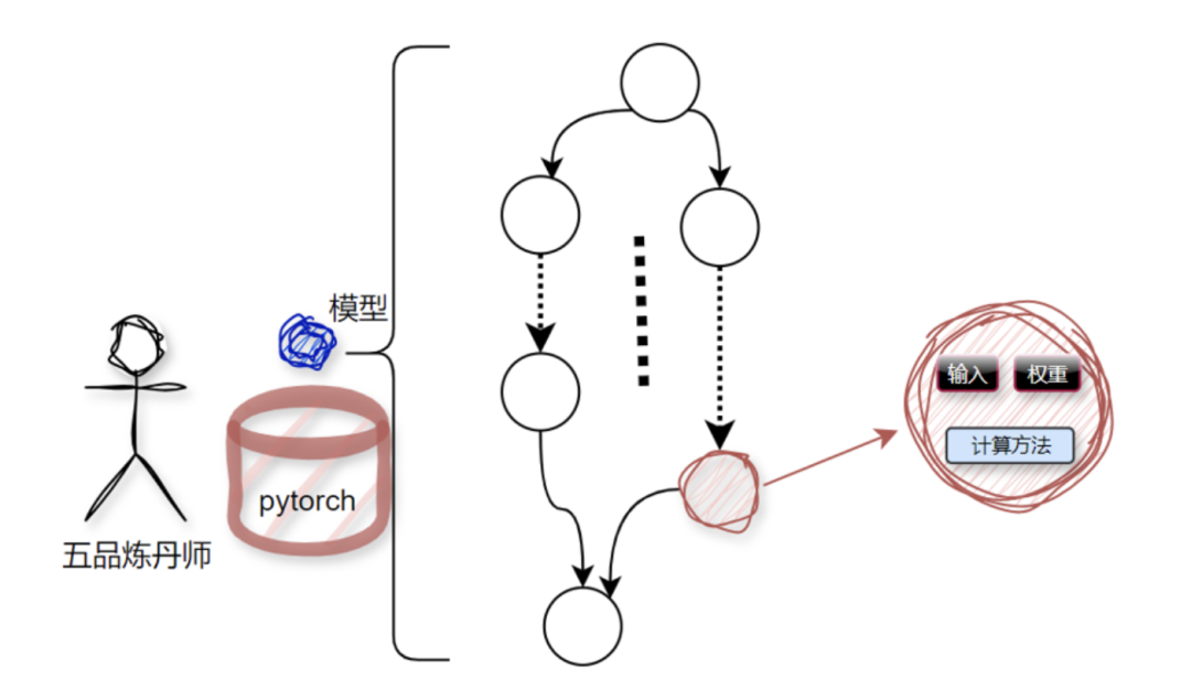
AI models are trained by incredibly intelligent algorithm engineers, commonly referred to as alchemists. The mainstream tools in the alchemy world are TensorFlow and PyTorch;
This alchemical process consists of a bunch of nodes, where nodes essentially process a bunch of data and the methods for computing this data, as shown in the diagram below:
 On a personal PC or server, running the entire model is very simple because the entire infrastructure has been established by major vendors (mainly NVIDIA), and we just need to use it. This is like finding a place to stay for a night; the most convenient and safe choice is to find a ready-made five-star hotel (the obvious downside is *), rather than building a house ourselves and moving in. Moreover, these AI deployment-related services have been validated by global developers over the years, making them easy and convenient. However, once you want to deploy it onto a specific, non-general-purpose hardware, the previous setup becomes completely useless. You need to “when in Rome, do as the Romans do” and use a software stack compatible with the specific hardware. Specifically for us here, that means using the Zhouyi SDK; if you want to run an AI model on the board, you need to learn how to use this SDK and the development methods.
3. Zhouyi SDK Introduction
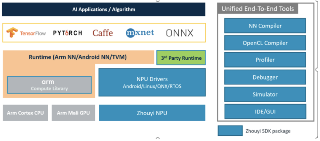
The usual practice is to first look at the overall process: first, assume you have obtained a trained model, such as model.onnx,
This model can only be in TensorFlow/PyTorch/Caffe/MXNet/ONNX format.
Then we use the toolchain in the SDK to compile model.onnx to get aipu.bin, like this:
aipubuild build.cfg
Finally, package this aipu.bin into the application program APP, and run it on the board;
In simple terms, the process is similar to compiling C code with gcc; only the parameter formats differ. Here, the input is the model, and the output is the NPU-supported executable bin file;
Additionally, there is a debugger available for debugging, performance issues can be handled with a profiler, and if there is no specific hardware, a simulator can be used to simulate the hardware. Of course, there is also a graphical IDE available for operations.
In future lessons, I will provide detailed explanations and code analysis for each module in conjunction with the SDK documentation. In this chapter, we will first follow the tutorial to walk through the process and get familiar with the code framework.
4. Operational Process + Initial Code Framework
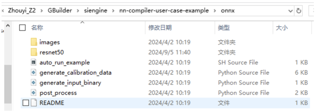
The second step is to compile the model, which is done on an x86 PC, following the link above (see the compilation part).
As seen in the above files, the first step is to generate a quantization calibration set, because our original model is in fp32, but the NPU does not support fp32, so we need to quantize it to int8/int16.
Quantizing an fp32 value to int8 involves a variety of algorithms in the quantization field. Here, we are using PTQ (don’t worry if you don’t understand this, I will explain the quantization-related content later, as this part of the code is open source, and we can even provide code-level explanations based on the open-source code).
Quantization requires a dataset to collect data range distribution. If you don’t understand why this step is necessary, that’s fine; just know that this process exists, and you’ll understand when we discuss quantization algorithms later.
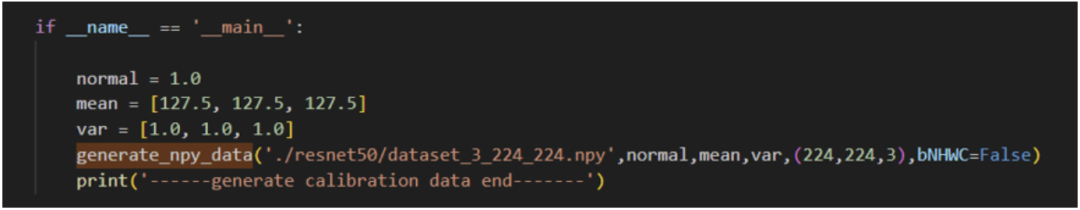
python3 generate_calibration_data.py
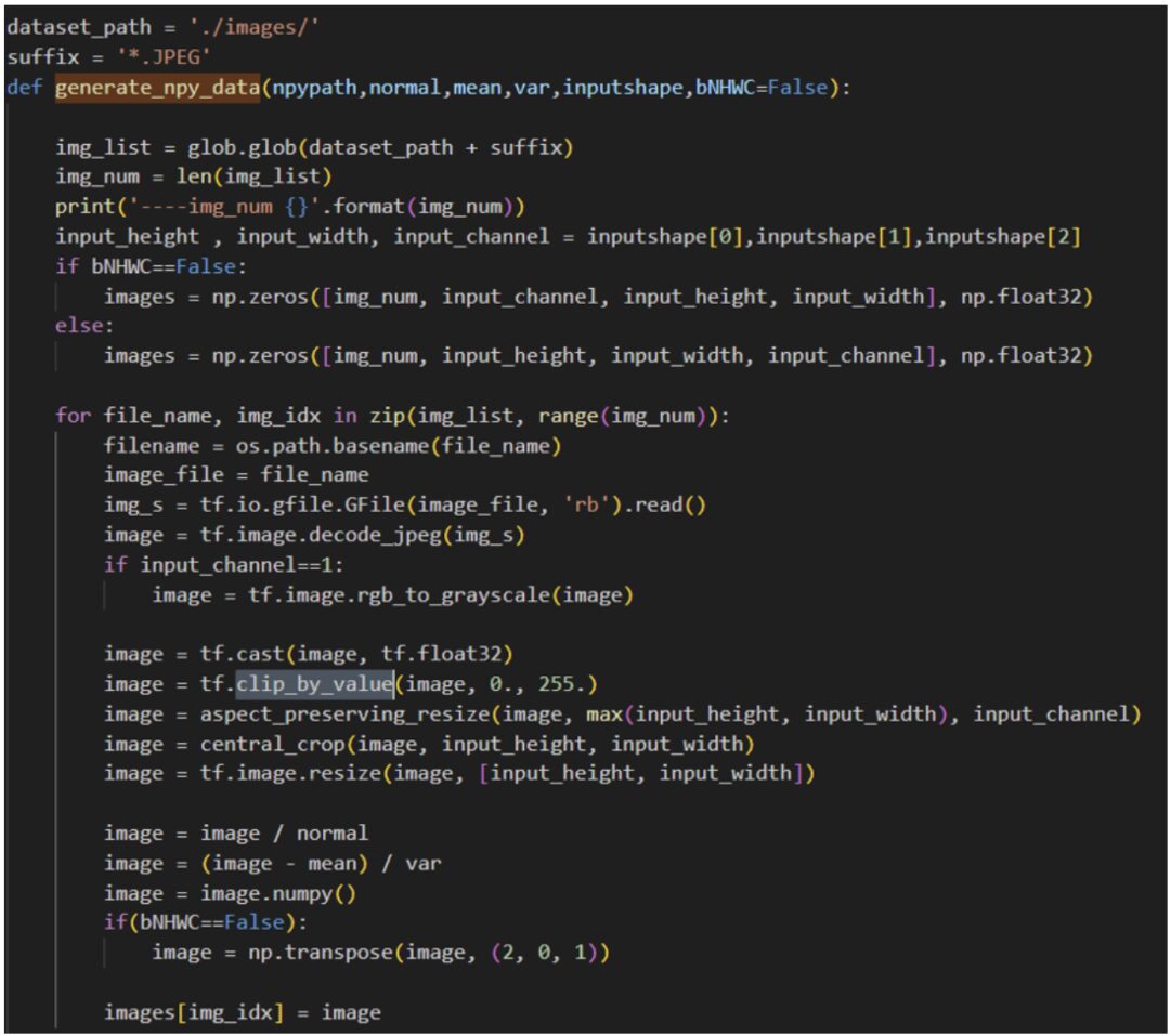
Let’s take a look at the implementation of the code.
It can be seen that this code is extracted from the original training code, processing the image set in the current directory to obtain the corresponding npy format data;
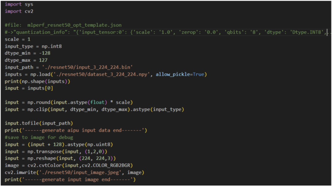
Next, we generate input data:
python3 generate_input_binary.py
Here, a brief explanation: first, we need to obtain a quantization parameter, which is the scale. This value is obtained from the quantization stage, and one of the files generated during quantization is the *.json file, which we can refer to.
Then we quantize the input image into uint8 format data, and transpose it to get the NHWC format input, which can now be used as input for the model (since the NPU-supported external input layout is NHWC),
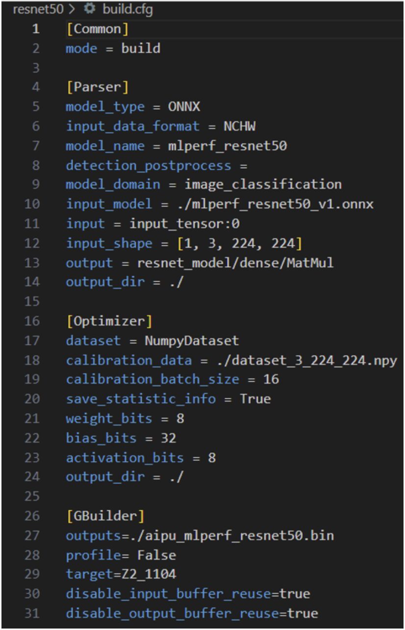
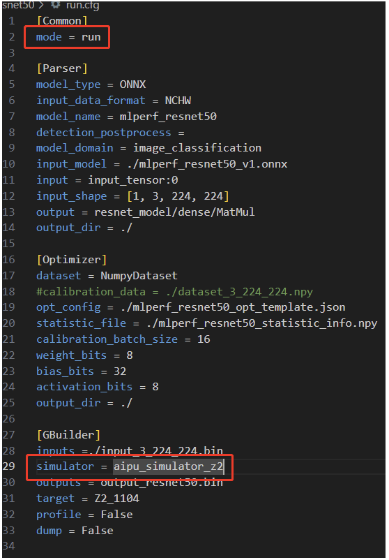
The second line of the compilation mode has two options: the first is build, which outputs aipu.bin for the board to run, and the second is run, which allows the compiled model to run directly on the server or local computer (simulator).
The compilation process consists of three major steps:
-
Parsing the model;
-
Quantization;
-
Compiling and executing;
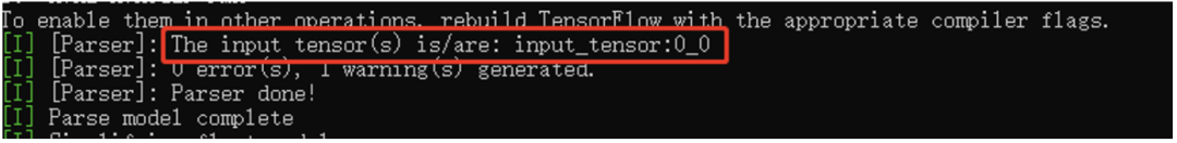
The parser’s role is to convert standard general models (ONNX, TF, PyTorch, etc.) into an internal dedicated IR; Input_data_format refers to the input data layout. We selected NHWC when constructing the input data, so we fill in NHWC here; the model name model_name can be filled in as standard; Detection_postprocess fills in the name of the post-processing operator, as detection models usually have a post-processing part; we can correspondingly fill it in or choose not to fill it and do post-processing directly on the CPU; the rest are as seen, except for the input configuration, which should be noted, as this is the name of the input tensor obtained by opening the onnx model in netron.
The Optimizer’s dataset field specifies the format of the dataset; since we constructed it in numpy format, we fill in NumpyDataset; the bits part is the only adjustable part for fine-tuning precision/performance trade-offs, and of course, if everyone wants to play later, I will guide you through the code-level approach.
The Gbuilder part is for direct compilation, while the profile outputs performance data, which can affect performance to some extent, so it should only be used during the debug phase; the target refers to the hardware version number, which should be filled in as Z2_1104, and there is no need for additional configuration in this section. However, we can provide detailed explanations for each parameter in the later Gbuilder chapters; for now, we’ll just briefly mention it.
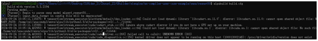
Compile directly according to the official tutorial:
As seen, the Gbuilder version is 5.3.2194, and the model parsing has begun. Since I am using WSL2 without CUDA, it will be relatively slow.
Once parsing is complete, we get the intermediate representation format (IR) required by our NPU.
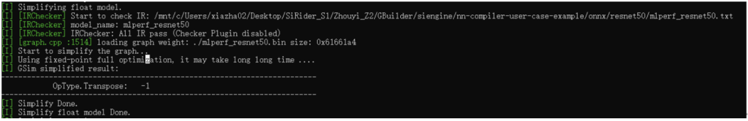
After obtaining the IR, we will first perform a check to see if the parsed IR format and graph connections are reasonable, and then conduct preliminary float graph-level optimizations, as seen, one Transpose layer has been optimized out;
Next, we enter the quantization phase. There are many stages in this entire process, and each stage has a specific task. We will set this aside for now, and later we will go through the source code step by step (if possible, we will also compare it with the well-developed PPQ framework in the industry).
The main focus here is on the final output scale, which will be used in the post-processing stage, as well as the cosine value of the output tensor, which reflects the model’s accuracy.
In summary, after quantization, we obtain the fixed-point format IR, which, after compilation, can run directly on the NPU hardware.
Since the graph structure may change during the quantization process, we need to perform graph checks and optimizations after quantization.
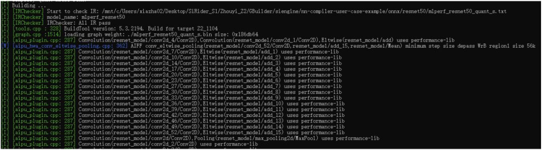
At this point, we have finally started compiling the model. This part mainly includes operator matching for nodes in the graph, memory allocation and optimization for the entire network, multi-core scheduling, and hardware-level graph optimization. For example, the aipu_plugin shown in the image above represents the operators, and each standard operator has several hardware implementations (OpenCL, ASM), which are matched globally based on specific mechanisms.
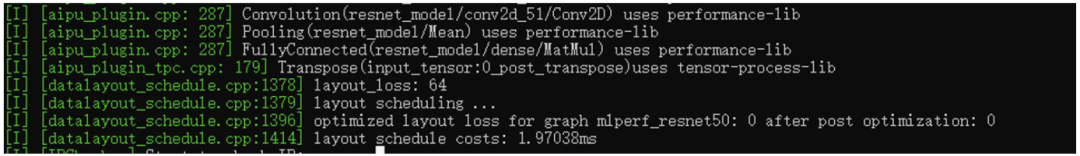
This is the layout scheduling part, and the goal is to minimize the number of layout conversions during the process. This part is also an optimization problem, and if we delve into it, it could go on indefinitely, but we will discuss it in detail later.
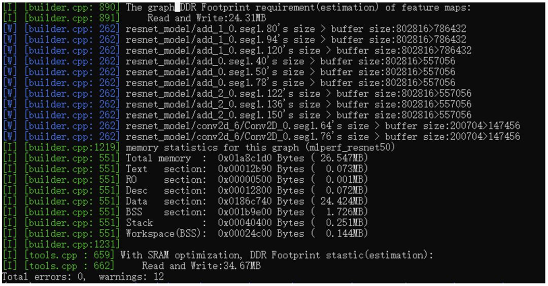
Finally, we will cover the memory aspect. The total memory required for the entire network is 26.547MB, including code segments, RO segments, desc segments (this is uncommon, as it is a specific format for underlying operators), and Data/BSS, which are standard formats. Lastly, it can be seen that there is an SRAM optimization, which is a fast static storage area within the NPU used to cache feature maps between nodes, which can reduce footprint and improve performance.
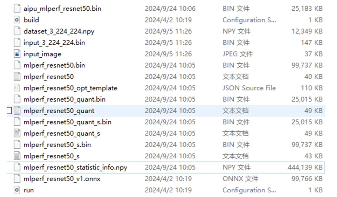
Alright, at this point, the model has finally been compiled. Let’s take a look at what has been generated:
 As you can see, besides the items in the red box, the rest are quite similar.
Now we have generated the model’s bin file, but it is still not the final executable application. The final application calls the model we just generated. The code for this part is as follows:
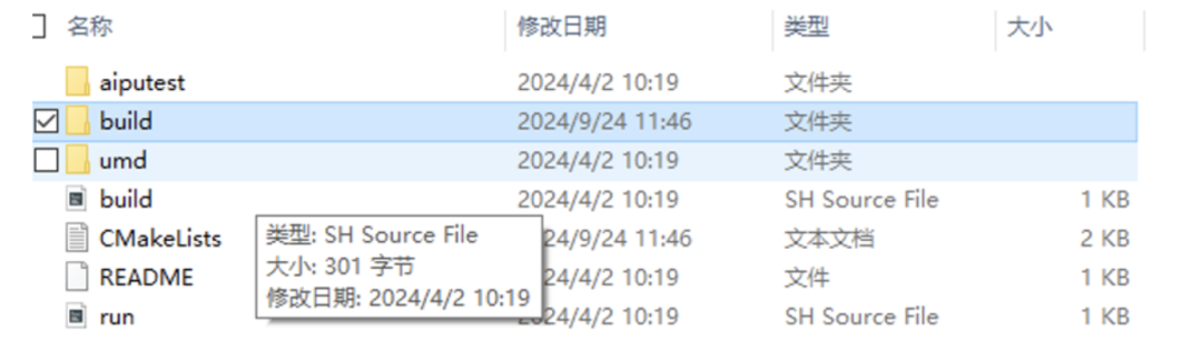
Aiputest is the logic part of the application, and the umd folder contains a bunch of user-facing library functions, which directly call drivers and environment setups (we will look at the code structure shortly).
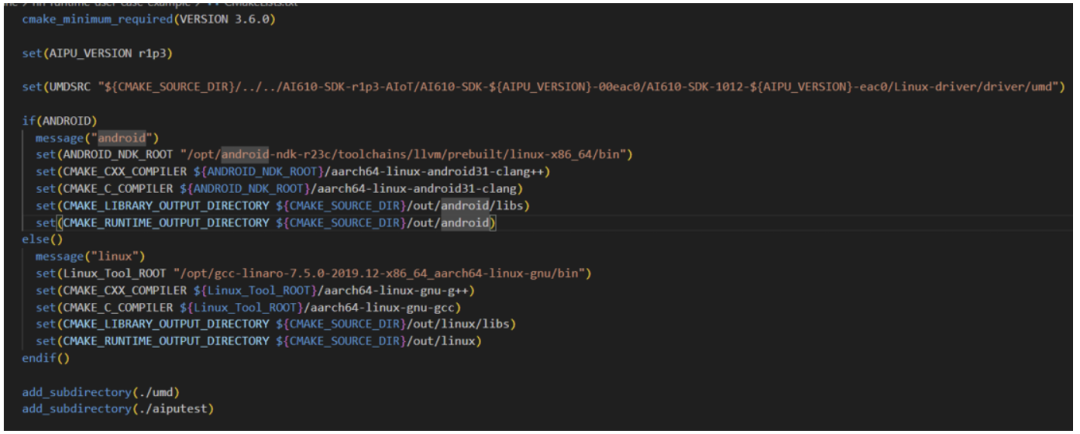
Following the structure of software engineering, we first check the top-level CMakeLists.txt file, and the information obtained is as follows:
Make sure the CMake version is correct, and carefully check the UMDSRC variable for the path! Set the path for the cross-compiler and the final output path;
After configuring the top-level parameters, directly add_subdirectory to let the subdirectory execute specific compilation tasks based on the parameters.
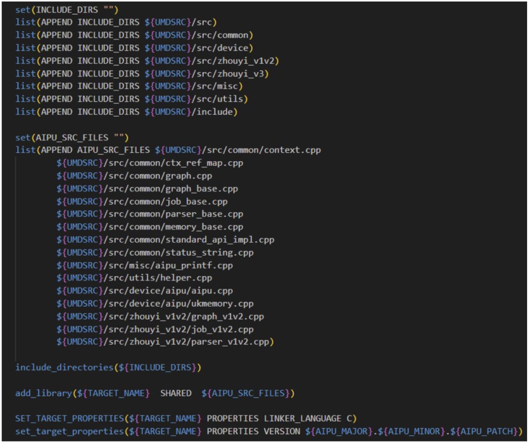
We first look at the umd folder, which directly pulls in the source code from Linux-driver/driver/umd to compile it into a dynamic library, linking it to the subsequent application aiputest.
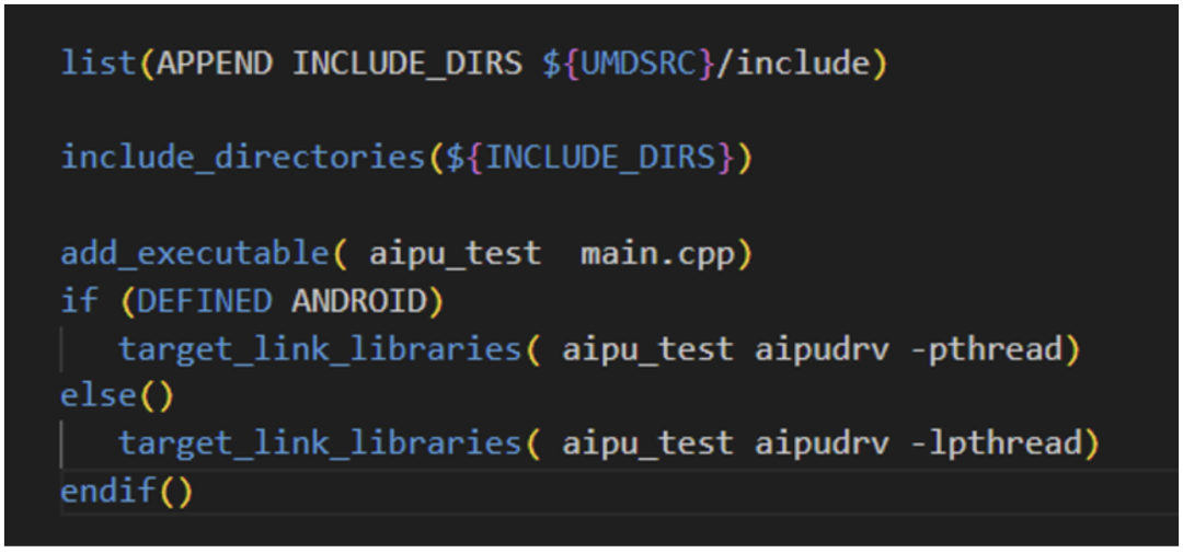
Aiputest is a very simple application, so we only need to include the umd header files and link the umd dynamic library to compile directly.
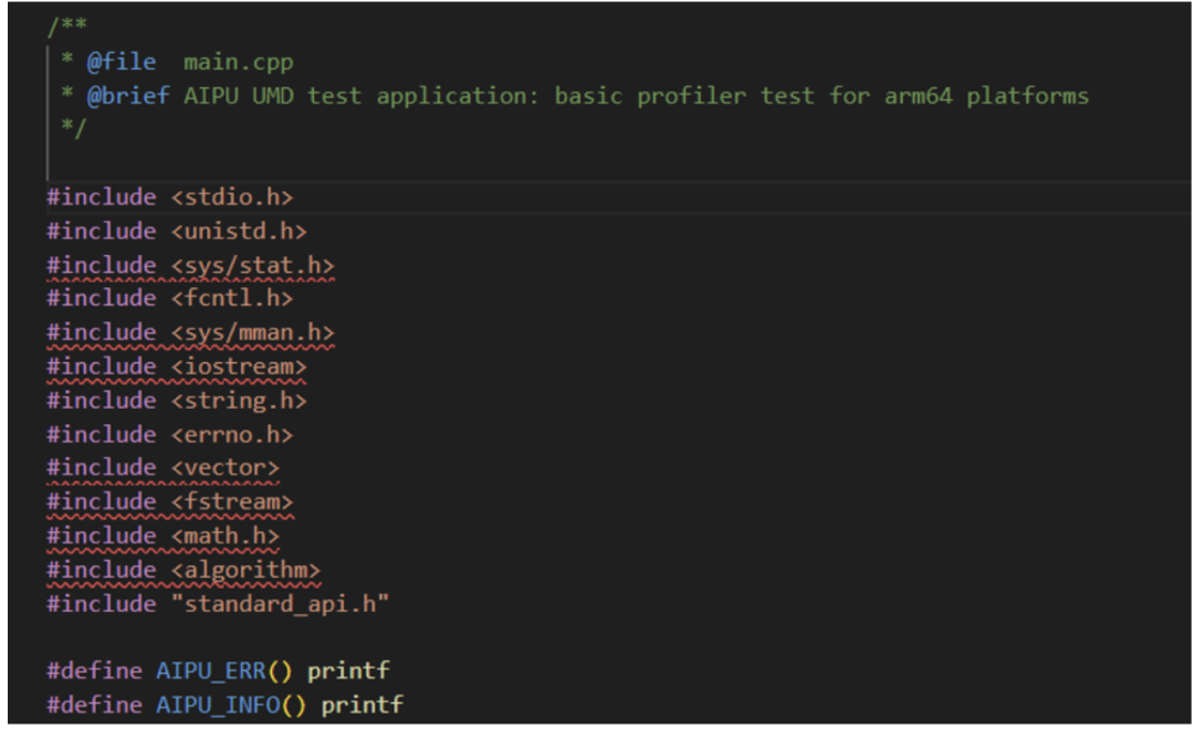
Let’s take a look at the content structure in the main.cpp file:
All UMD-related functionalities are encapsulated in the standard_api.h interface file. The subsequent code is merely about initializing the environment, starting the NPU task, receiving returned data, and cleaning up the “battlefield” (environment), which is nothing special. Specific parameter parsing can be found in the documentation or in my future articles for code-level analysis.
(ps. Although it is a C++ environment, it uses a very standard C coding style, which is great and very suitable for intuitive understanding of the execution process.)
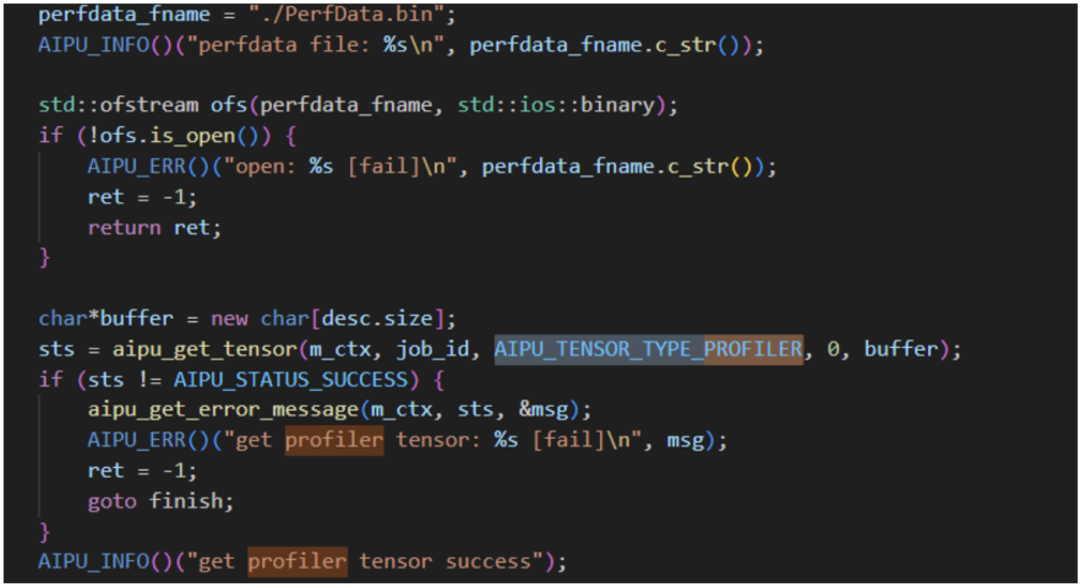
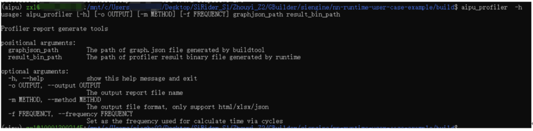
Researching the code reveals the logic for dumping the profiler;
The application also contains a profiler program, where result_bin_path refers to the PerfData.bin file outputted by the above code. So we can leave a note for later on how to use this for performance optimization analysis.
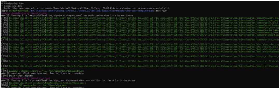
Alright, pulling back the perspective, we have directly compiled the corresponding files,
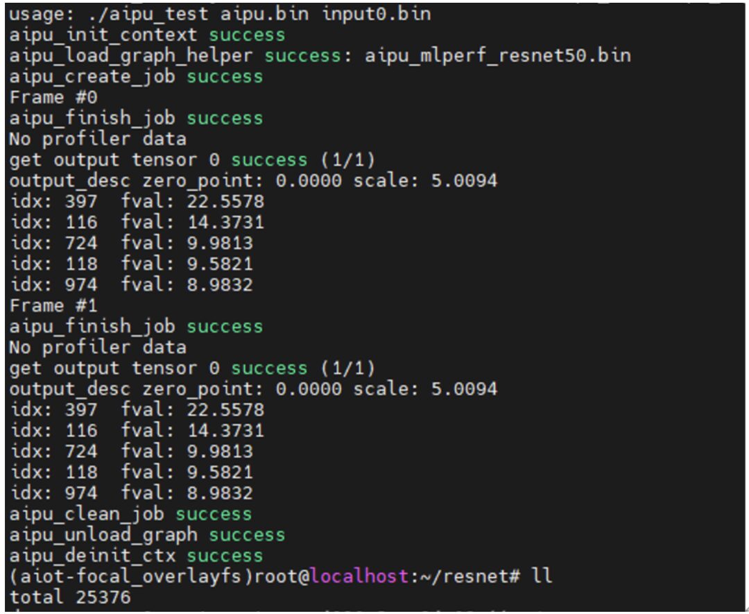
According to the official tutorial steps, after transferring the files to the board via scp, you can run it directly~
Next time, we will also discuss applications (focusing on quantization), explaining how to compile other models in model zoom and adjust their quantization accuracy, ultimately creating a slightly complete application.
As you can see, besides the items in the red box, the rest are quite similar.
Now we have generated the model’s bin file, but it is still not the final executable application. The final application calls the model we just generated. The code for this part is as follows:
Aiputest is the logic part of the application, and the umd folder contains a bunch of user-facing library functions, which directly call drivers and environment setups (we will look at the code structure shortly).
Following the structure of software engineering, we first check the top-level CMakeLists.txt file, and the information obtained is as follows:
Make sure the CMake version is correct, and carefully check the UMDSRC variable for the path! Set the path for the cross-compiler and the final output path;
After configuring the top-level parameters, directly add_subdirectory to let the subdirectory execute specific compilation tasks based on the parameters.
We first look at the umd folder, which directly pulls in the source code from Linux-driver/driver/umd to compile it into a dynamic library, linking it to the subsequent application aiputest.
Aiputest is a very simple application, so we only need to include the umd header files and link the umd dynamic library to compile directly.
Let’s take a look at the content structure in the main.cpp file:
All UMD-related functionalities are encapsulated in the standard_api.h interface file. The subsequent code is merely about initializing the environment, starting the NPU task, receiving returned data, and cleaning up the “battlefield” (environment), which is nothing special. Specific parameter parsing can be found in the documentation or in my future articles for code-level analysis.
(ps. Although it is a C++ environment, it uses a very standard C coding style, which is great and very suitable for intuitive understanding of the execution process.)
Researching the code reveals the logic for dumping the profiler;
The application also contains a profiler program, where result_bin_path refers to the PerfData.bin file outputted by the above code. So we can leave a note for later on how to use this for performance optimization analysis.
Alright, pulling back the perspective, we have directly compiled the corresponding files,
According to the official tutorial steps, after transferring the files to the board via scp, you can run it directly~
Next time, we will also discuss applications (focusing on quantization), explaining how to compile other models in model zoom and adjust their quantization accuracy, ultimately creating a slightly complete application.
Reprinted from | Jishu Community
Copyright belongs to the original author. If there is any infringement, please contact for deletion.
END


关于安芯教育


安芯教育是聚焦AIoT(人工智能+物联网)的创新教育平台,提供从中小学到高等院校的贯通式AIoT教育解决方案。
安芯教育依托Arm技术,开发了ASC(Arm智能互联)课程及人才培养体系。已广泛应用于高等院校产学研合作及中小学STEM教育,致力于为学校和企业培养适应时代需求的智能互联领域人才。