Follow+Star Public Number, don’t miss wonderful content

Source | Zhou Ligong
The RS-485 bus is widely used in communication, industrial automation, and other fields. In practical applications, it is often encountered whether to add pull-up and pull-down resistors and what size of resistors is appropriate. Below we will analyze these issues in detail.
Why are Pull-Up and Pull-Down Resistors Needed?
1. When the differential voltage of the 485 bus is greater than +200mV, the 485 transceiver outputs a high level;
2. When the differential voltage of the 485 bus is less than -200mV, the 485 transceiver outputs a low level;
3. When the voltage on the 485 bus is between -200mV and +200mV, the 485 transceiver may output either high or low level. However, it generally stays in one level state. If the output is low level, this is a start bit for UART communication, and communication will not be normal at this time.
When the 485 bus is open (the 485 transceiver is disconnected from the bus) or in an idle state (all 485 transceivers are in receive mode, and there are no transceivers driving the bus), the differential voltage of the 485 bus is basically 0, which puts the bus in an uncertain state. At the same time, due to the current design of 485 chips to increase the number of nodes on the bus, the input impedance is designed to be relatively high, for example, the input impedance is 1/4 unit impedance or 1/8 unit impedance (the unit impedance is 12kΩ, 1/4 unit impedance is 48kΩ), which makes it susceptible to electromagnetic interference when the pins are floating.
Therefore, to prevent the 485 bus from encountering the above situations, pull-up and pull-down resistors are usually added to the 485 bus (usually A connects to the pull-up resistor, and B connects to the pull-down resistor). If using an isolated RS-485 transceiver module (such as RSM485PCHT), since the module has built-in pull-up and pull-down resistors (for RSM485PCHT, the internal pull-up and pull-down resistors are 24kΩ), generally no additional pull-up and pull-down resistors are needed externally.
When is it Necessary to Add Pull-Up and Pull-Down Resistors?
When encountering signal reflection issues, matching resistors are usually added to avoid signal reflections. Taking 1-to-1 communication as an example, as shown in Figure 1. Since the 485 bus typically uses twisted pair cable with a characteristic impedance of 120Ω, 120Ω termination resistors should be added at both ends of the 485 bus to avoid signal reflection issues.
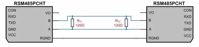 Figure 1: Communication Circuit of Two RSM485PCHT Modules
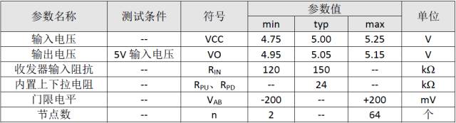
Based on the specific parameters of RSM485PCHT (as shown in Table 1), the equivalent circuit can be obtained as shown in Figure 2, where RPU and RPD are the pull-up and pull-down resistors added internally on the 485 bus, and RIN is the input impedance of the module.
Table 1 RSM485PCHT Parameters
Figure 1: Communication Circuit of Two RSM485PCHT Modules
Based on the specific parameters of RSM485PCHT (as shown in Table 1), the equivalent circuit can be obtained as shown in Figure 2, where RPU and RPD are the pull-up and pull-down resistors added internally on the 485 bus, and RIN is the input impedance of the module.
Table 1 RSM485PCHT Parameters
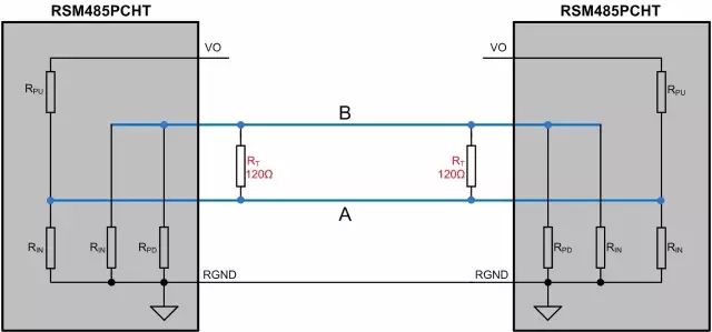 Figure 2: Communication Equivalent Diagram of RSM485PCHT
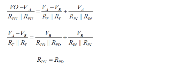
When both modules are in receive mode, Kirchhoff’s current law can be applied to nodes A and B to derive the following formulas:
Figure 2: Communication Equivalent Diagram of RSM485PCHT
When both modules are in receive mode, Kirchhoff’s current law can be applied to nodes A and B to derive the following formulas:
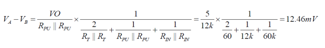
Based on the above formulas, the differential voltage between A and B can be calculated as:
At this point, the module is in an uncertain state, and the receiver of the module may output a high level or a low level. Therefore, it is necessary to add pull-up and pull-down resistors externally to ensure that the module does not remain in an uncertain state when idle.
How to Choose Pull-Up and Pull-Down Resistors?
Assuming the output power supply voltage V¬O of the module is the same, since RGND is connected together, the internal pull-up resistors of the module can be considered as being in parallel. For ease of explanation, the circuit in Figure 2 is organized as shown in Figure 3, where only one set of pull-up and pull-down resistors can be added externally, or pull-up and pull-down resistors can be added to each module. For convenience of explanation, we add a set of pull-up and pull-down resistors to the 485 bus.
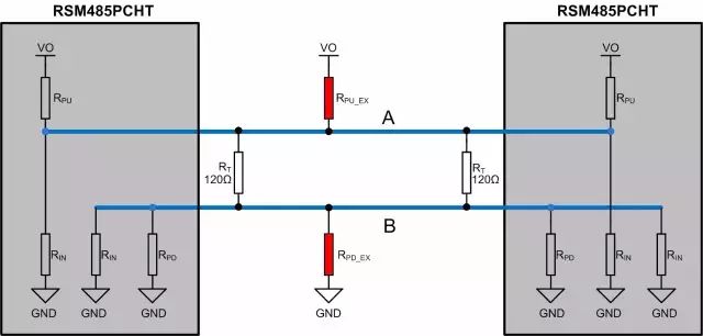 Figure 3: Communication Equivalent Circuit Diagram of RSM485PCHT
RPU is the internal pull-up resistor of the module, RPD is the internal pull-down resistor of the module, which in this case is 24kΩ;
RIN is the input impedance of the module, which in this case is taken as the minimum value of 120kΩ;
RT is the termination resistor, which in this case is taken as 120Ω;
RPU_EX is the external pull-up resistor added to the module, and RPD_EX is the external pull-down resistor added to the module;
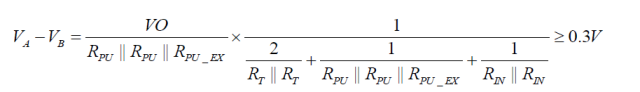
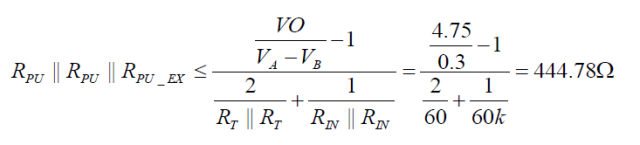
Since the threshold level of RSM485PCHT is -200mV to +200mV, generally a voltage margin of 100mV or 200mV is reserved. This example reserves a voltage margin of 100mV. Based on the previously derived differential voltage formula, the following calculation formula can be obtained:
Figure 3: Communication Equivalent Circuit Diagram of RSM485PCHT
RPU is the internal pull-up resistor of the module, RPD is the internal pull-down resistor of the module, which in this case is 24kΩ;
RIN is the input impedance of the module, which in this case is taken as the minimum value of 120kΩ;
RT is the termination resistor, which in this case is taken as 120Ω;
RPU_EX is the external pull-up resistor added to the module, and RPD_EX is the external pull-down resistor added to the module;
Since the threshold level of RSM485PCHT is -200mV to +200mV, generally a voltage margin of 100mV or 200mV is reserved. This example reserves a voltage margin of 100mV. Based on the previously derived differential voltage formula, the following calculation formula can be obtained:
Since RSM485PCHT operates within a power supply voltage range of 4.75V to 5.25V, taking VO=4.75V (the minimum input voltage VCC=4.75V), we can obtain:
Given RPU=24kΩ, we can find RPU_EX=RPD_EX=461.9Ω. Since the calculated resistance value is the maximum value, we can choose to add a single set of 410Ω or 390Ω pull-up and pull-down resistors to the 485 bus, or add two sets of 910Ω pull-up and pull-down resistors.
How to Verify the Value of Pull-Up and Pull-Down Resistors?
The above calculations only consider the idle state of the 485 bus being in a non-uncertain state and do not take into account the driving capability of the 485 transceiver and the power consumption of the components used. The smaller the external pull-up and pull-down resistors, the higher the differential voltage maintained in the idle state of the 485 bus, but at the same time, the power consumption of the termination resistor and pull-up and pull-down resistors increases, which also raises the driving capability requirements for the 485 transceiver. When exceeding the driving capability of the 485 transceiver, communication failures may occur.
According to the RS-485 standard, when the input impedance of the receiver is the unit impedance (minimum of 12k), a maximum of 32 nodes can be connected to the bus, and the maximum differential load of 485 is 54Ω. At this time, the minimum differential output voltage is 1.5V.
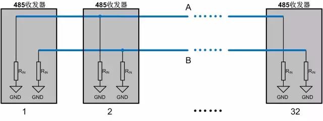 Figure 4: Equivalent Diagram of 485 Bus Connecting 32 Nodes
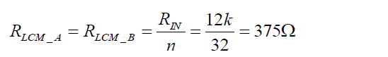
As shown in Figure 4, we can see that when there are 32 nodes connected to the 485 bus, the common-mode load of bus A or B is:
Figure 4: Equivalent Diagram of 485 Bus Connecting 32 Nodes
As shown in Figure 4, we can see that when there are 32 nodes connected to the 485 bus, the common-mode load of bus A or B is:
It can be seen that according to RS-485 standards, the maximum common-mode load of bus A or B is 375Ω.
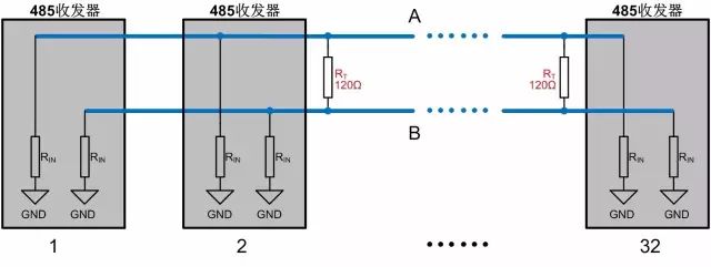 Figure 5: Equivalent Diagram of Adding Termination Resistors to the 485 Bus
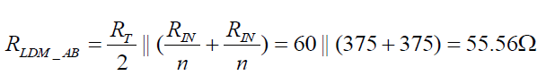
When termination resistors are added, it can be seen that the common-mode load of the 485 bus does not change, but the differential load decreases sharply. The differential load is:
Figure 5: Equivalent Diagram of Adding Termination Resistors to the 485 Bus
When termination resistors are added, it can be seen that the common-mode load of the 485 bus does not change, but the differential load decreases sharply. The differential load is:
Therefore, when the number of nodes on the 485 bus reaches the maximum and termination resistors are added, the differential load of the 485 bus still exceeds 54Ω. According to RS-485 standards, the minimum differential output voltage is 1.5V.
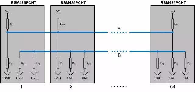 Figure 6: Equivalent Diagram of RSM485PCHT with 64 Nodes
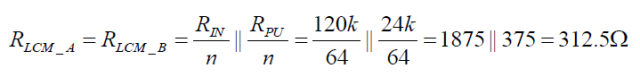
Taking RSM485PCHT as an example to illustrate the situation of adding pull-up and pull-down resistors, as shown in Figure 6, the common-mode load of bus A or B is:
Figure 6: Equivalent Diagram of RSM485PCHT with 64 Nodes
Taking RSM485PCHT as an example to illustrate the situation of adding pull-up and pull-down resistors, as shown in Figure 6, the common-mode load of bus A or B is:
Actual testing of the above situation shows that the minimum differential voltage output is 3.02V, which is much greater than the minimum differential output voltage of 1.5V specified by RS-485 standards.
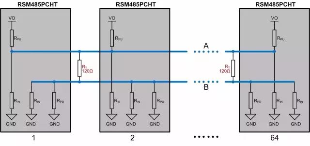 Figure 7: RSM485PCHT Adding Termination Resistors with 64 Nodes
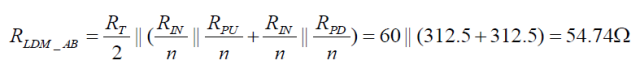
When termination resistors are added to the 485 bus, it can be observed that the common-mode load of bus A or B does not change, while the differential impedance changes significantly. At this point, the differential load is:
Figure 7: RSM485PCHT Adding Termination Resistors with 64 Nodes
When termination resistors are added to the 485 bus, it can be observed that the common-mode load of bus A or B does not change, while the differential impedance changes significantly. At this point, the differential load is:
The calculated differential load is slightly greater than the maximum load specified by RS-485 standard, which is 54Ω. We conducted actual tests on RSM485PCHT, and its output differential voltage was 1.58V, slightly greater than the minimum voltage specified by the standard.
When the differential load is 54Ω (the 485 bus connects two 120Ω termination resistors and the parallel value of the pull-up resistor (pull-down resistor) and transceiver internal resistance is 270Ω), the differential output voltage of RSM485PCHT is 1.52V (measured value), which is basically the same as the RS-485 standard.When the differential load is 41.54Ω (the 485 bus connects two 120Ω termination resistors and the parallel value of the pull-up resistor (pull-down resistor) and transceiver internal resistance is 135Ω), the differential output voltage of RSM485PCHT is about 1.17V (measured value), under this condition communication is possible.However, the maximum differential load specified in the 485 transceiver chip manual is usually 54Ω, which means that after adding two 120Ω termination resistors to the 485 bus, the parallel value of the pull-up resistor (pull-down resistor) and transceiver input impedance should be greater than 270Ω.To ensure stable and reliable communication, the parallel value of the pull-up resistor (pull-down resistor) and transceiver input impedance on the 485 bus should generally be greater than 375Ω.
1. Communication lines should use shielded twisted pairs, and the shield should be grounded at a single point;
2. When we do not encounter signal reflection issues, it is best not to use termination resistors;
3. If termination resistors are used, we can adjust the voltage value of the 485 bus in idle state through pull-up and pull-down resistors to ensure it does not remain within the threshold level (-200mV to +200mV or -200mV to -40mV);
4. When we add pull-up and pull-down resistors, the parallel value of the pull-up resistor (pull-down resistor) and transceiver input impedance should be greater than 375Ω.
Disclaimer: The materials in this article are sourced from the internet, and the copyright belongs to the original author. If there are any copyright issues regarding the works, please contact me for deletion.
———— END ————
● Column “Embedded Tools”
● Column “Embedded Development”
● Column “Keil Tutorial”
● Selected Tutorials from the Embedded Column
Follow the public account reply “Join Group” to join the technical exchange group according to the rules, reply “1024” to see more content.
Click “Read the Original” to see more shares.