Skip to content
SPI is very common in embedded systems, whether in system processors on chips (such as ARM, MIC, or high-end 32-bit processors like Power PC), or in microcontrollers (such as AVR, PIC, etc.), which typically include SPI controllers capable of operating in master-slave mode.
Programmable AVR controllers in the system can be programmed using the SPI interface; designs based on chips or FPGAs sometimes use SPI for communication. When we want to quickly transfer data to peripheral devices and have real-time requirements, SPI is a commonly used technology.
Besides SPI, there are many serial interfaces, such as Morse telegraph, RS232, USB, FireWire, Ethernet, etc. For many designs, each serial interface has its own advantages and disadvantages, and how to choose depends on factors like required data rate, space availability, and noise considerations.
SPI, or Serial Peripheral Interface, is designed to replace parallel interfaces, eliminating the need to route parallel buses on the PCB during design. It provides high-speed data transfer between devices. Motorola was the first company to name SPI as a circuit technology. This technology was applied in the late 1970s in the first 68000-based MCU for connecting peripheral devices, and later adopted by other companies in the industry. The simplicity and speed of the interface make communication or data transfer easy, making it a popular communication protocol.
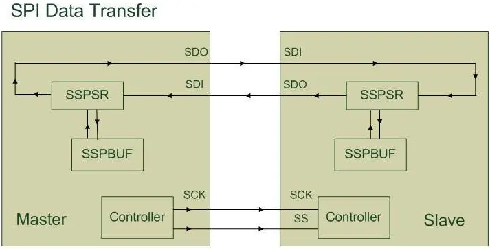
SPI is a simple 4-wire serial communication interface that allows communication between controllers and peripherals. In SPI, data is input/output at a rate of 1 bit per clock cycle, allowing for short-distance, high-speed data transfer between the master device and one or more slave devices. It is based on an 8-bit shift register that shifts data out to one output pin and shifts data in from another input pin.
Another feature of SPI is that it does not have the concept of bus ownership for transmission, meaning there is no change of master nodes, and there are no slave addresses. SPI is a simpler protocol, allowing for work frequencies higher than 10MHz (higher than TWI’s frequency).
Some features that contribute to the widespread use of SPI are:
-
Full-duplex communication;
-
Throughput higher than TWI;
-
Transmission is not limited to 8-bit words;
-
Simple hardware interface;
-
Flexible message size, content, and destination;
-
Usually meets low power requirements;
-
Slaves use the clock generated by the master, requiring no precise oscillator;
-
Lower power requirements than TWI due to fewer circuits.
However, comparing the TWI serial interface with SPI is unfair. They each have their own application domains, depending on system requirements.
TWI has the following characteristics:
-
Fewer pins on IC packages compared to SPI;
-
Hardware flow control exists;
-
It has a formal standard, unlike SPI;
-
It gives the slave address before communication.
Why is SPI most commonly used in PCBs?
Although SPI was primarily developed for communication between host processors and peripherals, it is also possible to connect two processors via SPI. The SPI bus is typically used only on PCBs; there are many obstacles to using SPI outside the PCB domain.
First, SPI is designed for high-speed data transfer between different IC chips; due to the high-speed requirement, the bus length cannot be too long, or it will become unusable due to increased reactance.
Of course, using low-speed SPI outside the PCB is possible, but it is not very practical. Peripheral devices can include real-time clocks, converters (such as ADCs and DACs), memory modules (such as EEPROM and FLASH), sensors (such as temperature sensors and pressure sensors), or other devices (such as signal mixers, potentiometers, LCD controllers, UART, CAN controllers, USB controllers, and amplifiers).
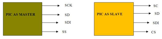
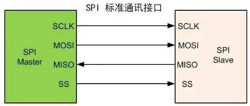
The SPI protocol includes the following 4 signal lines:
-
MOSI (Master Out Slave In)
The MOSI signal is generated by the Master, with the receiver being the Slave;
-
MISO(Master In Slave Out)
The Slave generates the MISO signal, with the receiver being the Master;
SCLK is generated by the master to synchronize data transmission between the master and slave;
The SS signal is generated by the master to select a single slave.
Sometimes serial data input [SDI] is used for MOSI, and serial data output [SDO] for MISO.
A master controller can communicate with multiple SPI peripherals, generally configured in two ways:
-
Cascaded slave configuration;
-
Parallel slave configuration.
Cascaded Slave Configuration
Cascaded slaves connect all the clock lines (SCLK) and chip select (CS) together. Data is transmitted from the microcontroller to each peripheral, eventually returning to the microcontroller. The data output from the previous slave connects to the data input of the next slave, forming a wider shift register. Therefore, cascaded slaves are treated as a larger device, connecting the same chip select signal.
This means that the master only needs to generate one SS line, instead of generating a separate SS line for each slave.
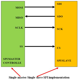
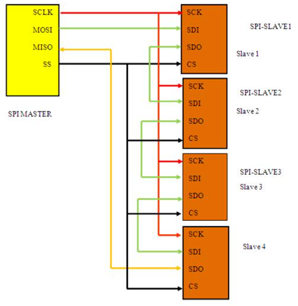
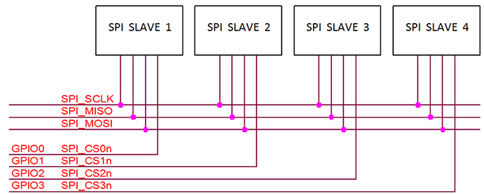
Parallel Slave Configuration
This is a typical SPI bus configuration, consisting of one master and multiple slaves. In this independent or parallel slave configuration:
-
All clock lines (SCLK) are connected together;
-
All MISO data lines are connected together;
-
All MOSI data lines are connected together.
SPI communication is always initiated by the master. First, the master generates a clock, with the clock frequency less than or equal to the maximum frequency supported by the slave; then the master controls data transmission by generating the clock signal (SCLK) and communicates by pulling down the chip select (SS) line of a specific slave. Slaves on the bus that are not selected by the master will ignore the input clock and MOSI signals from the master and must not drive MISO; this means the master selects only one slave at a time.
The use of the four pins depends on the device. For example, some devices do not require input (such as ADC), so the SDI pin may not exist, or some devices do not require output (such as LCD controllers), so the SDO pin may not exist. If a microcontroller only needs to communicate with one SPI peripheral, then the CS pin on that slave can be grounded (CS active low). For multiple slaves, each slave needs a separate CS signal.
What is the significance of tri-state output in SPI?
In digital electronics, tri-state logic allows output ports to adopt a high-impedance state in addition to 0 and 1 logic levels. This allows multiple circuits to share a single output line. Most peripherals have tri-state outputs, and when a device is not selected, the output enters a high-impedance state (disconnected). Devices without tri-state outputs cannot share the SPI bus with other devices.
SPI devices sometimes use another signal line to send interrupt signals to the host CPU. Examples of using interrupt signals include temperature alarms from temperature sensors, alarms from real-time clock chips, and headphone jack insertion detected by mobile phone audio codecs.
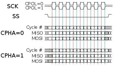
Another pair of parameters called clock polarity (CPOL) and clock phase (CPHA) determine the edges of the clock signal that drive and sample the data. In addition to setting the clock frequency, the master must also configure the clock polarity (CPOL) and phase (CPHA). Since the clock serves as the synchronization for data communication, based on CPOL and CPHA, there are four possible modes that can be used in the SPI protocol.
The full-duplex capability makes SPI very efficient for master/slave application scenarios, enabling efficient and fast data flows for applications like digital audio and digital signal processing.
SPI is used for communication with various peripherals, such as:
-
Temperature, pressure, ADC, touchscreen, video game controllers;
-
Audio codecs, digital potentiometers, DAC;
-
-
Ethernet, USB, USART, CAN handheld video games;
-
-
-
LCDs, sometimes even used for managing image data;
-
Any MMC or SD card (including SDIO variants);
-
For high-performance systems, FPGAs sometimes use SPI as a slave interface for the host, as a master interface for sensors, or as an import interface for flash memory.
Source:
www.engineersgarage.com/spi-what-is-serial-peripheral-interface-protocol