In embedded development, handling asynchronous events is an unavoidable challenge. For instance, reading sensor data from an accelerometer to calculate steps, or triggering RTOS context switches via timers, all rely on the support of exception handling mechanisms. Today, we will discuss the exception handling model of ARM Cortex-M.
The Core of Exception Handling
In the Cortex-M architecture, an exception refers to an event that interrupts the normal execution flow of a program. Simply put, while a program is running, an external event may suddenly interrupt it, such as a hardware interrupt, a system fault, or a special instruction triggered by software. According to ARM’s official documentation, exceptions are a broad concept, and interrupts are just one type of exception.
The core of exception handling lies in the ability to flexibly respond to asynchronous events. Imagine you are developing a smart wristband, where the step counting function requires real-time reading of accelerometer data, and in low-power mode, the system needs to be woken up periodically. All of these depend on the exception handling mechanism to ensure timely responses to events without disrupting the main program flow.
The exception handling mechanism of Cortex-M is fundamentally consistent across ARMv6-M, ARMv7-M, and ARMv8-M architectures, with a few minor differences that I will point out separately. Next, we will break down the entire mechanism step by step, from the types of exceptions and configuration methods to advanced features and practical coding.
Classification and Basic Concepts of Exceptions
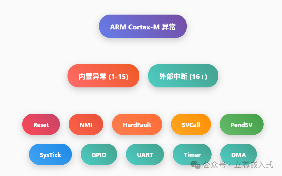
Cortex-M exceptions can be divided into two main categories:<span>Built-in Exceptions</span> and <span>External Interrupts</span>.
Each type of exception has three key attributes:
1. Exception Number
A unique identifier starting from 1, used to locate the exception handling function (also called ISR, Interrupt Service Routine) in the vector table. The vector table is like a phone book; when an exception is triggered, the hardware uses the exception number to find the corresponding handler address and jumps to execute it.
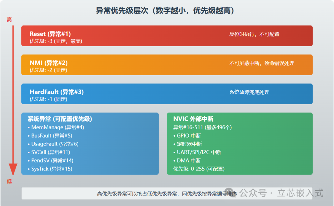
2. Priority Determines the Execution Order of Exceptions
Priority is represented by a number,<span>the smaller the number, the higher the priority</span>. For example, an exception with priority 1 will execute before one with priority 2. If two exceptions have the same priority, the one with the smaller exception number will execute first.
3. Synchronous or Asynchronous
Synchronous exceptions (like SVCall) are triggered immediately after a specific instruction is executed; asynchronous exceptions (like external interrupts) can be triggered at any time.
Built-in Exceptions
Built-in exceptions are those that come with the Cortex-M core, with exception numbers ranging from 1 to 15. Here are the six core exceptions supported by all Cortex-M:
- Reset: The first function executed when the chip is powered on or reset, with exception number 1, the highest priority, and non-configurable.
- NMI (Non-Maskable Interrupt): As the name suggests, it cannot be masked, with priority just below Reset. It is typically used to handle critical errors, such as when other exception handling functions fail.
- HardFault: A catch-all for system faults, such as accessing illegal memory, division by zero, or unaligned access. On ARMv6-M, HardFault is the only fault handling entry; on ARMv7-M and ARMv8-M, more granular fault handling can be enabled (like MemManage, BusFault, UsageFault).
- SVCall: An exception triggered by the SVC instruction, commonly used for implementing system calls in RTOS.
- PendSV and SysTick: Software-triggered system-level interrupts, commonly seen in RTOS scheduling and context switching. PendSV is particularly suitable for deferring the handling of low-priority tasks.
External Interrupts
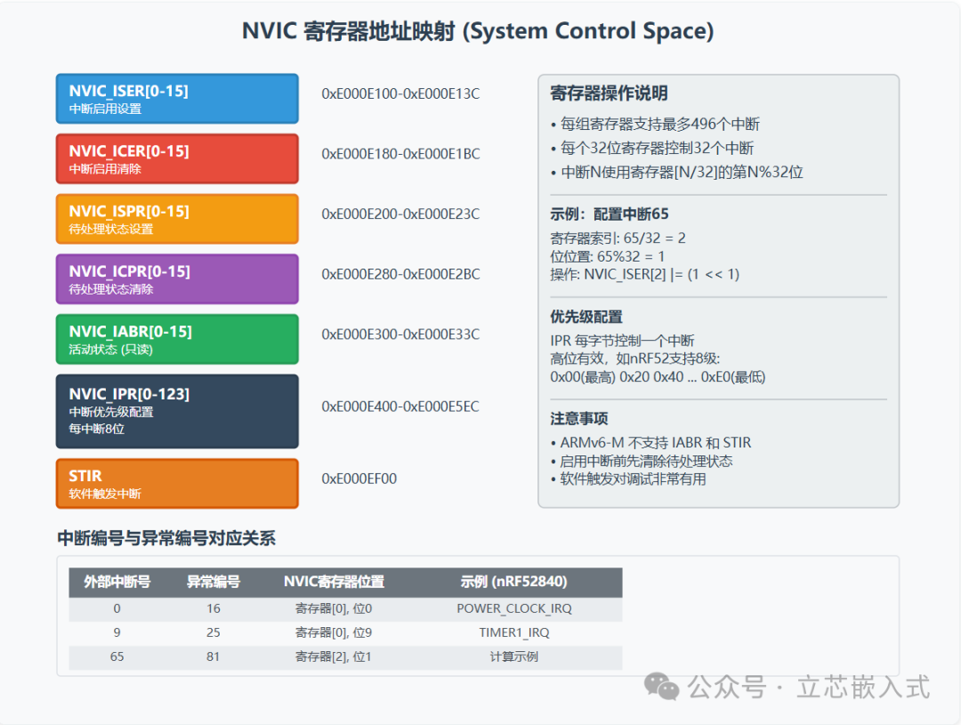
External interrupts are triggered by specific peripherals from chip manufacturers, such as DMA, GPIO, or UART, with exception numbers starting from 16. These interrupts are uniformly managed by the NVIC (Nested Vectored Interrupt Controller). The NVIC acts like a smart scheduler, responsible for enabling, disabling, setting priorities, and managing the nesting and preemption of interrupts.
The number of external interrupts supported varies significantly across different Cortex-M models. ARMv6-M (like Cortex-M0) supports a fixed number of 32, while ARMv7-M and ARMv8-M can support up to 496! The specific number can be calculated by reading the ICTR register (address 0xE000E004):<span>Number of interrupts = 32 * (INTLINESNUM + 1)</span>.
Configuring Exception Registers
Exception configuration mainly relies on a set of registers in the System Control Space (SCS). Here are the functions and usage points of several core registers to help you get started quickly.
1. ICSR (Interrupt Control and State Register)
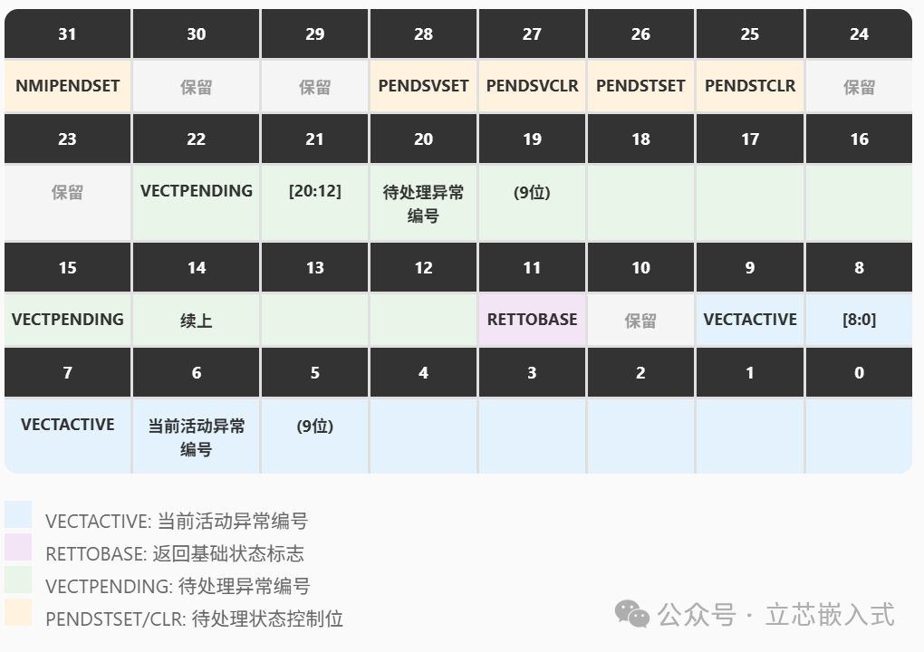
ICSR is the dashboard for exception states, allowing control over NMI, PendSV, SysTick, etc., and viewing the current interrupt status. Key fields include:
- VECTACTIVE: The number of the currently active exception, 0 indicates no active exception.
- RETTOBASE: When 0, it indicates that another exception is active, meaning preemption has occurred. ARMv6-M does not support this field.
- VECTPENDING: The number of the highest priority pending exception, 0 indicates no pending exceptions.
2. AIRCR (Application Interrupt and Reset Control Register)
AIRCR provides system-level control functions, with key fields:
- SYSRESETREQ: Writing 1 triggers a system reset, calling the reset handler.
- PRIGROUP: Configures the grouping method for priorities, dividing them into group priorities and sub-priorities. Group priority determines preemption, while sub-priority determines execution order within the same group. ARMv6-M does not support this field.
- VECTKEY: When writing to the register, 0x05FA must be filled in as a key to prevent accidental operations.
3. SHPR1-SHPR3 (System Handler Priority Registers)
Used to set the priority of built-in exceptions, such as SVCall, PendSV, etc. Each exception occupies 8 bits, with a default priority of 0 (highest). Note: The priorities of Reset, NMI, and HardFault are non-configurable, and writing to SHPR0 has no effect.
4. SHCSR (System Handler Control and State Register)
Used to enable or view the status of built-in exceptions, such as MemManage, BusFault, etc. ARMv6-M only supports the SVCALLPENDED field.
In fact, the NVIC also has a set of registers, and there is too much content, so here is a diagram for you:
Some Advanced Features
The exception handling in Cortex-M is not just a simple jump to execute the ISR; it also has many hardcore advanced features:
1. Exception Entry and Exit
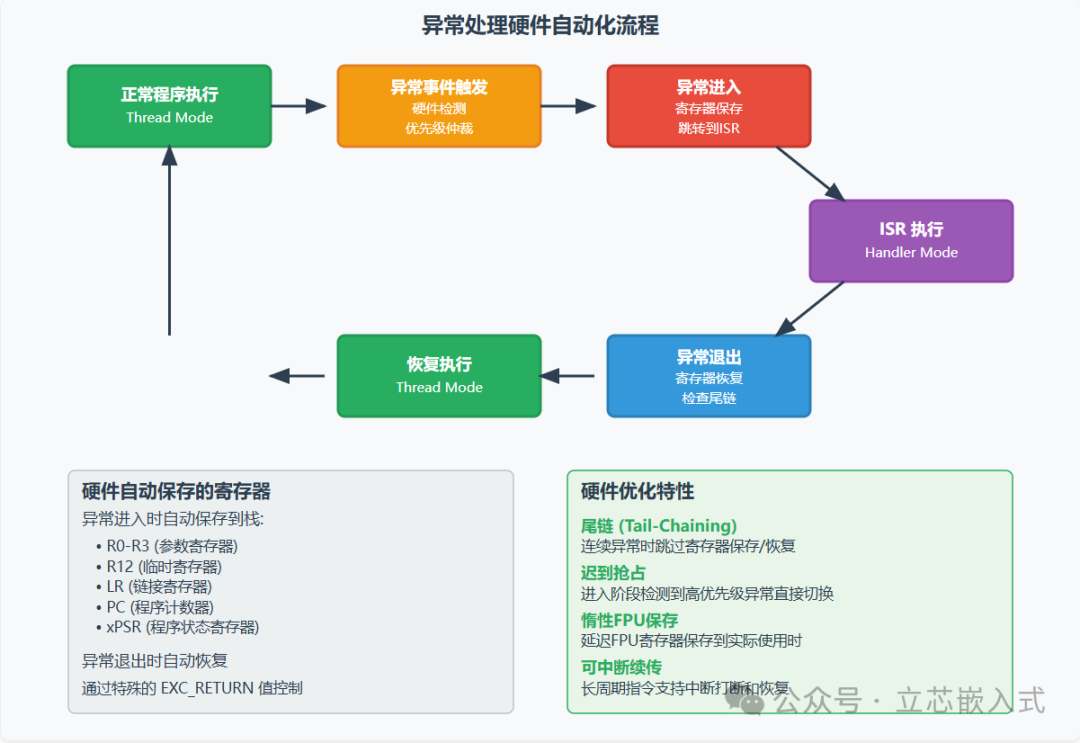
The ARM exception entry mechanism follows the AAPCS (ARM Architecture Procedure Call Standard), where the hardware automatically saves the caller registers (R0-R3, R12, LR, PC, xPSR) and encodes the EXC_RETURN value in LR for restoring the context upon exception exit. This means that exception handling functions can be directly written in C without needing assembly intervention, greatly simplifying development. Compared to other architectures (like some 8-bit MCUs), Cortex-M’s exception handling is incredibly user-friendly.
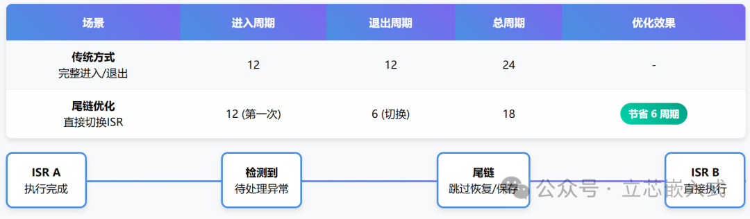
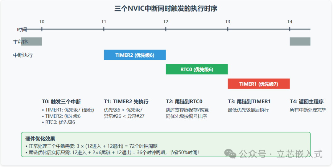
2. Tail-Chaining
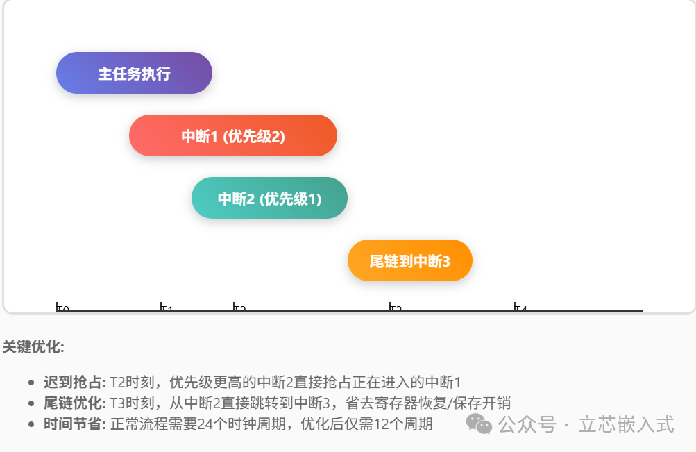
Tail-chaining is a remarkable optimization in Cortex-M. When an ISR exits, if another exception is pending, the hardware skips the register restoration and saving steps, directly entering the next ISR. For example, in Cortex-M3, a normal entry and exit from an ISR takes 12 clock cycles, while tail-chaining only takes 6 cycles, saving a total of 18 cycles! This can significantly reduce latency in high-frequency interrupt scenarios.
3. Late-arriving Preemption

If a higher-priority exception is detected during the exception entry phase (when saving registers or fetching the ISR address), the hardware will directly switch to the higher-priority ISR, skipping the completed register saves. After completion, it can tail-chain to the originally planned lower-priority ISR. This optimization further reduces the latency of high-priority interrupts.
4. Lazy State Preservation

ARMv7-M and ARMv8-M support optional Floating Point Units (FPU), which bring 33 additional registers (s0-s31 and fpscr). Saving these registers during exception entry can increase latency. Lazy state preservation optimizes latency by delaying the saving of FPU registers (until the ISR uses floating-point instructions). For ISRs that do not use the FPU, this can save the overhead of saving and restoring 17 registers. Additionally, context switching in RTOS requires an extra 132 bytes of stack space for FPU state, and effectively utilizing lazy preservation can significantly reduce the risk of stack overflow.
5. Priority Boosting
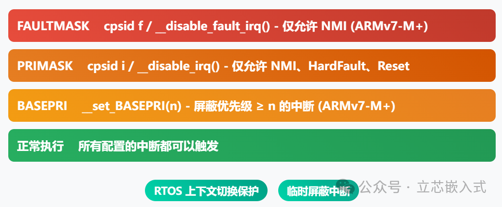
Sometimes it is necessary to temporarily mask certain interrupts, such as during RTOS context switching. Cortex-M provides three ways to boost execution priority:
- PRIMASK: Disables all configurable priority interrupts via
<span>__disable_irq()</span>or<span>cpsid i</span>, allowing only NMI, HardFault, and Reset. - FAULTMASK: Disables all interrupts except NMI via
<span>__disable_fault_irq()</span>or<span>cpsid f</span>. ARMv6-M does not support this. - BASEPRI: Sets a priority threshold via
<span>__set_BASEPRI()</span>, masking interrupts below that threshold. Setting it to 0 is ineffective, and ARMv6-M does not support this.
6. Interruptible Load/Store Instructions
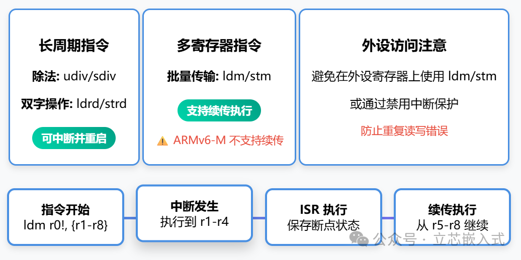
Most ARM instructions are atomic, but for long-cycle instructions (like division udiv/sdiv or double-word load/store ldrd/strd), Cortex-M allows interrupts to interrupt and restart upon return. Some instructions (like ldm/stm) support interruptible execution, meaning they can continue from the breakpoint after an interrupt. ARMv6-M does not support this and will restart the instruction directly.
Note: When accessing memory areas that may cause errors due to repeated reads/writes (like peripheral registers), avoid using ldm/stm, or protect these operations by disabling interrupts.
Practical Coding
Having discussed the theory, let’s move on to the main event—practical coding! We will use the nRF52840 as an example to demonstrate how to trigger built-in exceptions and NVIC external interrupts.
Preparation
Most SDKs provide a default vector table, and exception handling functions are usually defined as weak symbols, making them easy to override. For example, the vector table for nRF52840 is in <span>gcc_startup_nrf52840.S</span>:
.section .isr_vector
.align 2
.globl __isr_vector
__isr_vector:
    .long   __StackTop
    .long   Reset_Handler
    .long   NMI_Handler
    .long   HardFault_Handler
    ...
    .long   SVC_Handler
    .long   DebugMon_Handler
    .long   PendSV_Handler
    .long   SysTick_Handler
    .long   POWER_CLOCK_IRQHandler  /* Exception Number 16 */
    .long   RADIO_IRQHandler
    ...
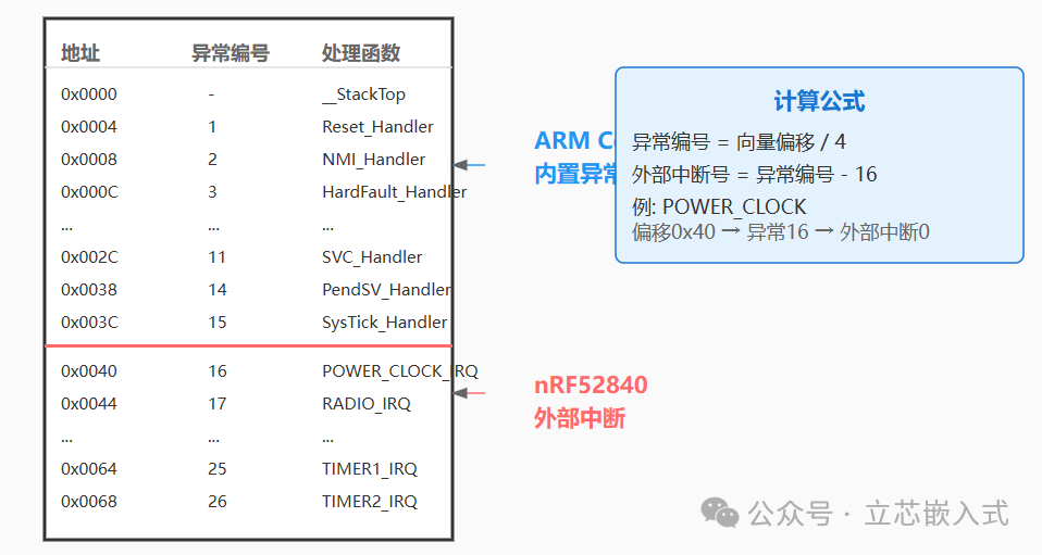
The exception number is calculated from the vector table offset: Reset is 1, POWER_CLOCK is 16. The SDK also provides an <span>IRQn_Type</span> enumeration that defines external interrupt numbers (exception number – 16), which can be found in <span>nrf52840.h</span>.
Note: The default exception handling function (including HardFault) is usually an infinite loop <span>while(1)</span>, meaning that when a fault occurs, the chip can only recover by manual reset or power-off. It is recommended to override the fault handling function to at least trigger a system reset to give the chip a chance to recover.
nRF52840 supports 8 priority levels (0-7), which can be confirmed by debugging the NVIC_IPR register:
(gdb) p/x *(uint32_t*)0xE000E400
$1 = 0x0
(gdb) set *(uint32_t*)0xE000E400=0xff
(gdb) p/x *(uint32_t*)0xE000E400
$2 = 0xe0
Returning 0xe0 indicates that the high 3 bits are valid, supporting 8 priority levels.
Example 1: Triggering PendSV Exception
PendSV is commonly used for RTOS context switching; we will trigger it via software and debug with breakpoints:
void PendSV_Handler(void) {
    __asm("bkpt 1");
}

__attribute__((optimize("O0")))
static void trigger_pendsv(void) {
    volatile uint32_t *icsr = (void *)0xE000ED04;
    *icsr = 0x1 << 28; // Set PENDSVSET bit
    __asm("isb"); // Flush pipeline
}
In the main loop, call <span>trigger_pendsv()</span>, and GDB outputs:
Program received signal SIGTRAP, Trace/breakpoint trap.
PendSV_Handler () at main.c:48
48    __asm("bkpt 1");
(gdb) p/x (*(uint32_t*)0xE000ED04)&0xff
$2 = 0xe
(gdb) p/x (*(uint32_t*)0xE000ED04)>>11&0x1
$3 = 0x1
(gdb) p/x (*(uint32_t*)0xE000ED04)>>12&0xff
$4 = 0x0
VECTACTIVE is 0xe (PendSV), RETTOBASE is 1 (no other active exceptions), and VECTPENDING is 0 (no pending exceptions), which meets expectations.
Example 2: NVIC Interrupt Preemption
We will configure the POWER_CLOCK interrupt (external interrupt 0, exception number 16) and trigger PendSV within it to verify preemption:
__attribute__((optimize("O0")))
void POWER_CLOCK_IRQHandler(void) {
    __asm("bkpt 2");
    trigger_pendsv();
    __asm("bkpt 3");
}

static void trigger_nvic_int0(void) {
    volatile uint32_t *nvic_ipr = (void *)0xE000E400;
    *nvic_ipr = 0xe0; // Set lowest priority
    volatile uint32_t *nvic_iser = (void *)0xE000E100;
    *nvic_iser |= 0x1; // Enable interrupt
    volatile uint32_t *nvic_ispr = (void *)0xE000E200;
    *nvic_ispr |= 0x1; // Trigger interrupt
    __asm("isb");
}
Call <span>trigger_nvic_int0()</span>, and GDB outputs:
Program received signal SIGTRAP, Trace/breakpoint trap.
POWER_CLOCK_IRQHandler () at main.c:53
53    __asm("bkpt 2");
(gdb) p/x *(uint32_t*)0xE000ED04
$1 = 0x810
VECTACTIVE is 0x10 (POWER_CLOCK). Continuing execution to PendSV:
Program received signal SIGTRAP, Trace/breakpoint trap.
PendSV_Handler () at main.c:38
38    __asm("bkpt 1");
(gdb) p/x *(uint32_t*)0xE000ED04
$2 = 0xe
(gdb) p/x *(uint32_t[16] *)0xE000E300
$3 = {0x1, 0x0 <repeats 15>}
PendSV preempted execution, and NVIC_IABR confirms that POWER_CLOCK is still active. Continuing execution returns to POWER_CLOCK:
POWER_CLOCK_IRQHandler () at main.c:55
55    __asm("bkpt 3");
(gdb) p/x *(uint32_t*)0xE000ED04
$5 = 0x810
The preemption and return process is perfectly validated.
Example 3: Simultaneously Triggering Three NVIC Interrupts
Finally, we will trigger three interrupts (TIMER1, TIMER2, RTC0, external interrupts 9-11, exception numbers 25-27) to verify priority ordering:
void TIMER1_IRQHandler(void) { __asm("bkpt 4"); }
void TIMER2_IRQHandler(void) { __asm("bkpt 5"); }
void RTC0_IRQHandler(void) { __asm("bkpt 6"); }

static void trigger_nvic_int9_int10_int11(void) {
    volatile uint32_t *nvic_ipr2 = (void *)(0xE000E400 + 8);
    *nvic_ipr2 |= (0x7 << 6) << 8;  // TIMER1 priority 7
    *nvic_ipr2 |= (0x6 << 6) << 16; // TIMER2 priority 6
    *nvic_ipr2 |= (0x6 << 6) << 24; // RTC0 priority 6
    volatile uint32_t *nvic_iser = (void *)0xE000E100;
    *nvic_iser |= (0x1 << 9) | (0x1 << 10) | (0x1 << 11);
    volatile uint32_t *nvic_ispr = (void *)0xE000E200;
    *nvic_ispr |= (0x1 << 9) | (0x1 << 10) | (0x1 << 11);
    __asm("isb");
}
After calling, GDB outputs:
Program received signal SIGTRAP, Trace/breakpoint trap.
TIMER2_IRQHandler () at main.c:81
81    __asm("bkpt 5");
(gdb) p/x *(uint32_t*)0xE000ED04
$9 = 0x41b81a
(gdb) p/d (*(uint32_t*)0xE000ED04)&0xff
$10 = 26
(gdb) p/d (*(uint32_t*)0xE000ED04)>>12&0xff
$12 = 27
TIMER2 (priority 6, exception number 26) executes first, as its number is lower than RTC0 (priority 6, exception number 27). VECTPENDING confirms that RTC0 is pending. Continuing execution:
Program received signal SIGTRAP, Trace/breakpoint trap.
RTC0_IRQHandler () at main.c:86
86    __asm("bkpt 6");
(gdb) c
Program received signal SIGTRAP, Trace/breakpoint trap.
TIMER1_IRQHandler () at main.c:76
76    __asm("bkpt 4");
The execution order is TIMER2 → RTC0 → TIMER1, consistent with the priority and number rules.