1 8-Bit/16-Bit Bus Timing Analysis
1.1 8-Bit Microcontroller Bus Timing
There are many 8-bit microcontrollers with external buses, such as the 51 series and AVR series. This article takes the W77E58 as an example. The W77E58 is an enhanced 51 microcontroller introduced by Winbond, with a maximum operating clock of 40 MHz. At the same clock frequency, the instruction speed of the W77E58 is three times that of traditional 51 microcontrollers. Additionally, the addressing capability of the program memory and data memory for the W77E58 is 64KB. The upper half of Figure 1 shows the read timing, while the lower half shows the write timing.
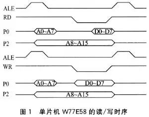
Taking data reading as an example, ports P0 and P2 output the current address, and the falling edge of ALE latches the low 8 bits of the address, while the high 8 bits remain unchanged. After that, the read signal RD is enabled (low level), and the external device sends data to port P0. The rising edge of RD reads the data into the microcontroller. Writing data is similar, but the data direction is reversed. To ensure that the data can be correctly written into the external device, the microcontroller sends data to port P0 before enabling the write signal WR, and WR must remain inactive for a certain time. As shown in Figure 1, the microcontroller accesses 8-bit data using port P0, while port P2 is only used for address output.
1.2 IDE Hard Drive Bus Timing
Next, we analyze the 16-bit bus timing using the IDE hard drive as an example. Figure 2 is a schematic diagram of the IDE hard drive interface [1], showing only the signal lines related to the bus: DIOR/DIOW for read/write; DCS0/DCS1 for chip select; DD0-DD15 for 16-bit data lines; DA0-DA2 for 3-bit address lines.
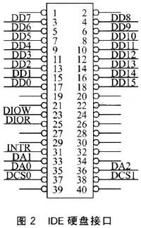
The IDE hard drive is a typical 16-bit bus device. The IDE interface has two chip select signals, with DCS1 used for addressing control registers. By default, access operations can be performed on the IDE hard drive, so this signal line is generally connected directly to a high level, only using DCS0. Its timing is shown in Figure 3.
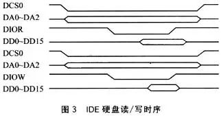
At the beginning of the read/write cycle, both DIOR and DIOW are in an invalid state, and DA0-DA2 connect to the address output of the host (in this case, the microcontroller). Upon receiving a read request (DIOR enabled), data is sent to the data line, and the host latches this data on the rising edge of DIOR. After that, the hard drive controller releases the data line after a delay. When receiving a write request (DIOW enabled), the data line is set to tri-state, waiting for the host to output data. Finally, on the rising edge of DIOW, the data is written into the hard drive controller. Before the rising edge of DIOW, the host must have the data ready.
Comparing Figures 1 and 3, we can see that the bus timing is basically consistent, differing only in the number of bits of data transmitted on the data line. However, a single instruction from the host completes a read/write cycle, and the 16-bit data from the external device to the host becomes invalid after the instruction is completed. In contrast, the data from the host to the external device must be ready before the instruction is completed. Therefore, to expand the 8-bit bus to a 16-bit bus, the data latching issue during read/write must be considered simultaneously.
2 Implementation of 16-Bit Bus Expansion
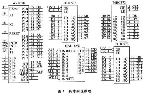
Based on the previous analysis of bus timing, the method shown in Figure 4 is adopted to expand the 8-bit bus to meet the requirements of 16-bit bus read/write. It mainly consists of the following two parts: 1 GAL16V8 (U5) for decoding chip select signals and encoding other signals; 2 pieces of 74HC573 (U3, U4) for latching the high 8-bit data. CS1-CS4 are the decoded outputs of A9-A15, which can connect to 4 external devices. The address range is set according to the specific devices, assuming that CS2 is connected to a 16-bit bus device:
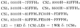
Here, “&” represents “AND,” and “!” represents “NOT,” meaning that when RD and CS5 are both active, LE5 is active; when WR and CS6 are both active, LE6 is active. Note that CS5 and CS6 have a portion of the address space that overlaps with CS2, meaning that selecting CS2 will also simultaneously select CS5 or CS6. Additionally, by connecting the external device address lines, the addressing of 8000H-81FFH and 8200H-83FFH points to the same location. For example, in Figure 2, DA0 -> A0, DA1 -> A1, DA2 -> A2.
When the microcontroller writes 16-bit data, it executes a write operation to enable CS6 (addressing FE00H-FFFFH), outputs the high 8-bit data, and latches it to U4. Then, it executes a write operation to enable CS2 (addressing 8200H-83FFH), synchronously outputting the data on port P0 and the latched data from U4, forming 16-bit data D0-D15, which is then written to the external device.
When the microcontroller reads 16-bit data, it executes a read operation to enable CS2 (addressing 8000H-81FFH), with the low 8 bits from the external device sent to port P0, while the high 8 bits are simultaneously latched by U3. It then executes a read operation to enable CS5 (addressing FC00H-FDFFH), sending the latched data from U3 to port P0.
In the above read/write process, although the addressing positions for CS2 are different (read for 8000H-81FFH, write for 8200H-83FFH), due to the overlap of positions, correct read/write to the 16-bit external device can be achieved. Furthermore, if the microcontroller is connected to 8-bit devices on CS1, CS3, and CS4, operations on them will not be affected because U3 and U4 are not enabled.
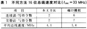
From the implementation above, it can be seen that the expanded 16-bit external bus only adds one instruction for data interaction with external devices. The comparison results of this method with conventional port simulation methods are listed in Table 1. As shown in the table, the transmission rate using this method is three times that of the conventional method.
Additionally, the aforementioned expansion method can be further extended: 1) If there are unused I/O ports (for example, the P1 port of W77E58), they can be used to directly output high 8-bit data, thus eliminating U4 in Figure 4; 2) If cost is not a major concern, the logic devices in Figure 4 can be implemented using CPLD, making the design more flexible, wiring more convenient, and structure more compact, while the basic implementation principle remains as shown in Figure 4.
3 Application in Onboard Data Acquisition System
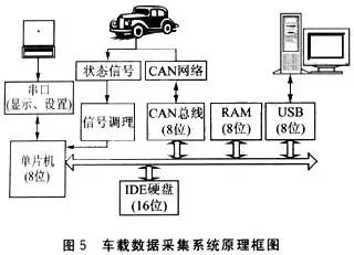
The method of expanding the 8-bit microcontroller to a 16-bit external bus has been applied in onboard data acquisition systems, with Figure 5 showing the principle block diagram of this system. When automotive manufacturers develop new models or upgrade key components, they must go through necessary stages such as sample trial production, product identification, small batch trial production, and mass production. Each stage is accompanied by a large number of reliability tests, and the onboard data acquisition system is designed for these tests. Given its special operating conditions, it must meet the following basic requirements: continuous, long-term data acquisition, which may last several days or even a month; because many vehicles may undergo testing simultaneously, the system must be low-cost, safe, and reliable, with a CAN bus data acquisition interface. In Figure 5, the 8-bit microcontroller is connected to three 8-bit bus devices (USB Slave device, RAM, and CAN bus device) and one 16-bit bus interface device (IDE hard drive).
The microcontroller uses the previously mentioned W77E58. To ensure a high data transmission rate and facilitate communication with external serial devices (LCM display), an external crystal frequency of 33 MHz is used.
The USB Slave device employs the PDIUSBD12, using a modular approach to implement a USB interface. This design maps the IDE hard drive as a removable drive, thus achieving mass storage class functionality.
The RAM used is HY62WT08081E. This device provides 32KB of data space for data acquisition and caching for FAT32 file system operations.
The CAN bus interface device uses a combination of SJA1000 and TLE6250. The SJA1000 is a standalone CAN controller used for controller area networks in automotive and industrial environments, while the TLE6250 is a CAN transceiver designed for automotive environments.
The IDE hard drive uses an industrial hard drive with shockproof treatment, but a CF card with IDE adapter can also be used.
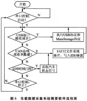
Figure 6 presents a brief software flowchart for the onboard data acquisition system. Considering that data requests from the USB port and CAN bus generally do not occur simultaneously, the software operates in a polling manner, mainly including the following parts: main flow, USB protocol implementation [2], CAN bus data [3], and other vehicle status signal acquisition, as well as FAT32 protocol implementation.
4 Summary
This design implements a 16-bit external bus on an 8-bit microcontroller, enabling high-speed access to 16-bit devices while retaining the functionality of the original 8-bit bus. This coexistence of 8-bit and 16-bit buses significantly enhances data transmission rates compared to conventional port simulation bus methods. This 16-bit bus expansion method has been successfully applied in onboard data acquisition systems, where multiple systems have been installed for automotive road reliability testing. Test results indicate that the system is easy to use, stable, reliable, and has a high data transmission rate, fully meeting the needs for dynamic data acquisition in vehicles. This 16-bit bus expansion method can be applied to microcontrollers with an 8-bit external bus, thereby expanding the application range of such microcontrollers to a certain extent.