 AbstractNature has evolved numerous design paradigms by organizing basic materials into complex structures. The damage-resistant double helix structure (double-bouligand) found in the scales of the coelacanth is composed of collagen fibers arranged in a double helical manner. This study applies the toughening mechanism of the double helix design to the preparation of structured concrete using large-scale dual-component robotic additive manufacturing technology. This process enables the precise construction of large, complex components. Compared to single helix structures, traditional orthogonal structures, and monolithic cast concrete, the double helix design exhibits a non-brittle response and an ascending resistance curve (R-curve), attributed to the hypothesized double-layer crack shielding mechanism. Furthermore, the interlocking effect induced behind the crack tip and the crack deflection in front of it in the double-layer double helix structure enhance its fracture toughness by 63% compared to monolithic cast concrete.Highlights of the Paper
- Environmental Sustainability: Discusses decarbonization strategies in the cement and concrete industry, carbon capture technologies, and the development of green building materials aimed at reducing the carbon footprint of construction.
- 3D Printing Technology: Covers advancements in large-scale 3D printed concrete, including material formulations, printing process optimization, and structural design, supporting remote and scalable construction.
- Robotic Automation: Involves multi-robot systems, collective robotic construction, and automated construction tools to enhance building efficiency and quality control.
- Artificial Intelligence Applications: Utilizes AI for structural design optimization, defect detection, and material performance prediction, achieving an intelligent construction process.
- Material Innovation and Recycling: Develops low-carbon cement, recycles waste materials, and optimizes material rheological properties to reduce construction waste and environmental impact.
Visual Overview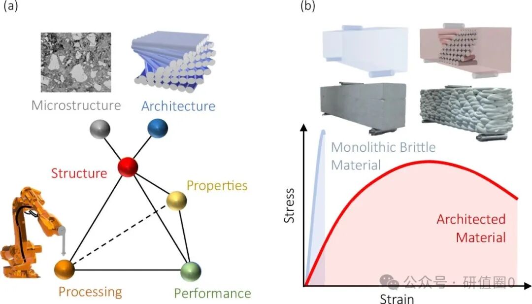 Figure 1: Engineering Material Performance Modulation through Microstructural Designa) A conceptual materials science tetrahedron characterizing the relationship between material processing-structure (micro/macro)-performance-exhibition;b) Schematic of enhanced mechanical response of structured materials compared to monolithic materials.
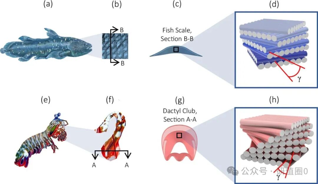 Figure 2: Two Biomimetic Configurations for Structured Concrete Developmenta) Actual image of the coelacanth (Latimeria Chalumnae) (© Encyclopedia Britannica, used with permission);b) Coelacanth scales;c) Schematic cross-section of fish scales;d) Model of collagen fiber bundles arranged in a helical pattern in fish scales (inter-fiber arrangement not shown), γ is the helical angle;e) Actual image of the mantis shrimp (Odontodactylus Scyllarus) (© Adobe Stock);f) Mantis shrimp raptorial appendage;g) Schematic cross-section of the raptorial appendage;h) Model of chitin fibers arranged in a helical pattern in the raptorial appendage, γ is the helical angle.
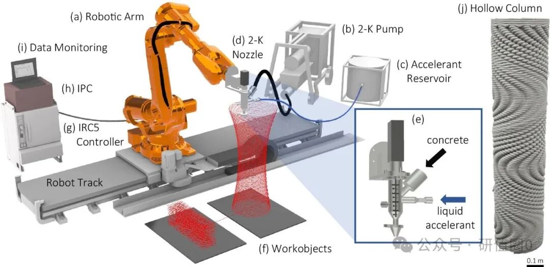 Figure 3: Schematic of the Dual-Component (2-K) Robotic Additive Manufacturing Processa) ABB IRB 6700 robot with a 5.7-meter rail system (working radius 2.85m, load capacity 150kg);b) Dual-component concrete pump with in-situ feeding;c) Accelerator storage tank and metering system;d) Dual inlet mixing chamber for concrete/accelerator;e) End effector of the printing nozzle;f) Work object with visual path planning;g) ABB IRC5 controller;h) Digital control system for concrete pump/accelerator flow and servo motors;i) Real-time monitoring interface for temperature/pressure sensors;j) Example of complex component manufacturing using the 2-K process: structured beams and hollow columns (which can serve as non-removable formwork).
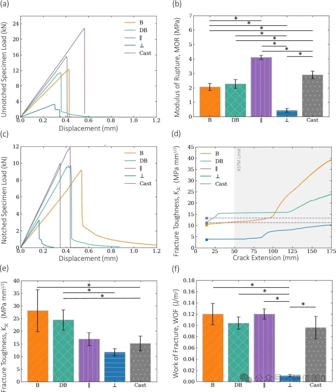 Figure 4: Comparison of Mechanical Responses and Fracture Properties of Four Structural Designs and Monolithic Cast Concrete(Comparison groups: parallel layered, vertical layered, single helix, double helix)a,b) Load-displacement curves and average fracture modulus of notched specimens;c) Load-displacement curves of notched specimens;d) R-curve of notched specimens (fracture toughness vs. crack extension), with dashed lines indicating the highest values for each design;e,f) Average toughness of notched specimens G_cGc and fracture work (WOF).Data format: mean ± standard deviation;indicates p<0.05 (F-test and T-test)
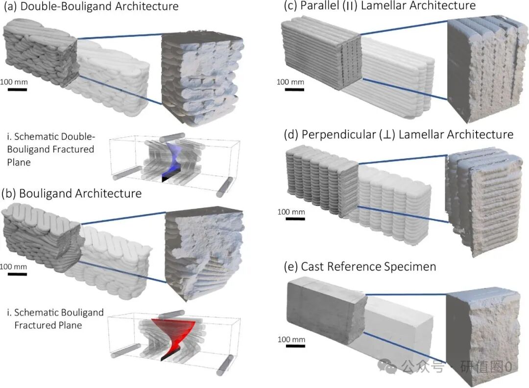 Figure 5: Comparison of Fracture Morphologies of Structured and Cast Concrete in SENB Testinga) Double helix structure (including i ideal fracture surface model);b) Single helix structure (including ii ideal fracture surface model);c) Parallel layered structure;d) Vertical layered structure;e) Monolithic cast reference group.
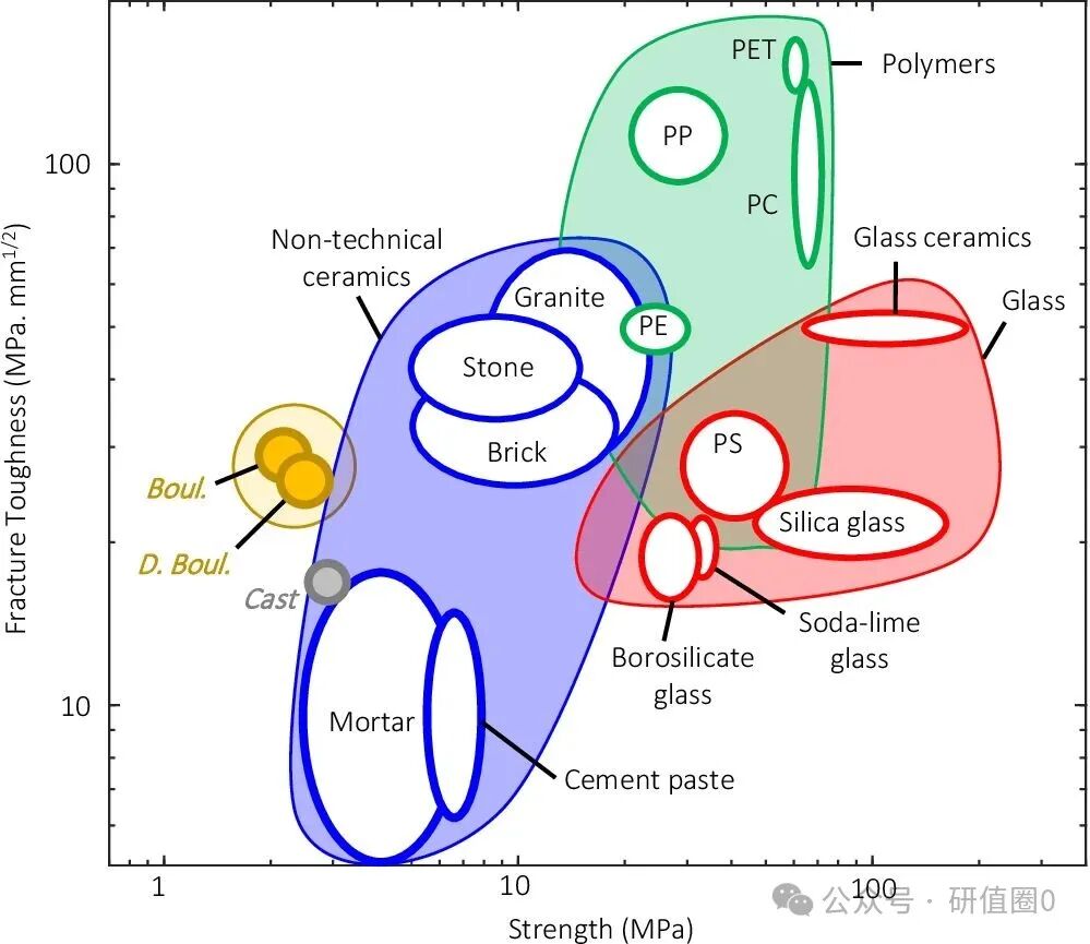 Figure 6: Ashby Material Selection Chart (Fracture Toughness vs. Strength)*Reference materials: polymers [66,67], glass [66,67], non-technical ceramics [66,68], cement paste [69,70], cement-based mortars [55,71-73];Materials in this study: cast group, single/double helix structured groups.Original DOI: https://doi.org/10.1038/s41467-024-51640-y If you enjoyed this, please follow us! All images and data in this article belong to the original authors and are for sharing and reading purposes only. If any related interests of the original authors are infringed, please notify us for deletion! Any omissions in the translation process are welcome for correction. QQ group – 782110223