1. Introduction
In electronic circuit design, there might be a situation where the microcontroller has no DAC resources and no spare PWM ports available. The only remaining option is a UART. So how can we output an analog voltage through this port?
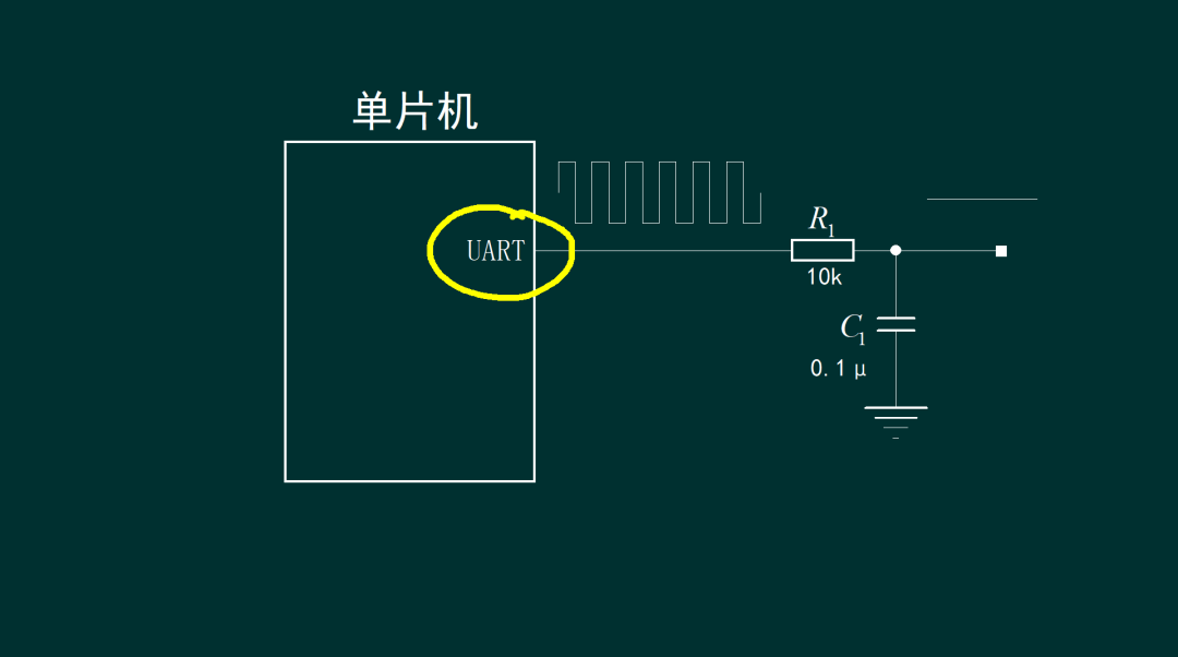
By using the microcontroller’s port, we can output a square wave signal with a variable duty cycle, which, after passing through an RC low-pass filter to remove the AC component, allows us to output the DC component of the square wave signal. The remaining question is, how do we use UART to output a square wave signal with a duty cycle that can be changed to a high level?
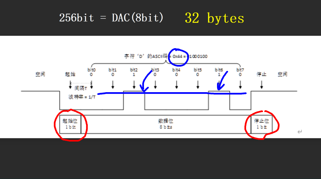
The signal waveform sent by the microcontroller’s UART includes a start bit and a stop bit, which are 0 and 1 respectively, and cannot be changed. The eight data bits in between can be modified. For example, sending 0x44 will include two high-level bits. This gives us 8 data bits that can be controlled as high or low. Thus, we can achieve a 3-bit DAC output. If we want to achieve an 8-bit DAC output, we need 256 controllable data bits. By combining 32 consecutive bytes, we can form a 256-bit signal waveform that can control high and low levels, thus achieving an 8-bit DAC output. Let’s test the performance of this UART output of analog signals using a microcontroller.
2. Test Circuit
A test circuit board based on STM32F103 was designed. I have many of these chips on hand, so I chose it for the experiment. UART2 is used for testing, while UART1 is used for program downloading. An RC low-pass filter is applied to the TXD2 signal. In fact, RXD2 is not used. Additionally, two ADC guiding ports are included. This allows the ADC to collect signals sent from outside and then send them out from TXD2, verifying the functionality of audio signal acquisition and synthesis. A single-sided test circuit board was laid out, which includes a flying wire using a 0-ohm resistor for the jumper.
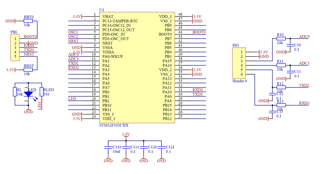
▲ Figure 1.2.1 Test Circuit Schematic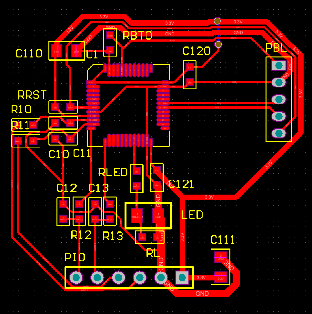
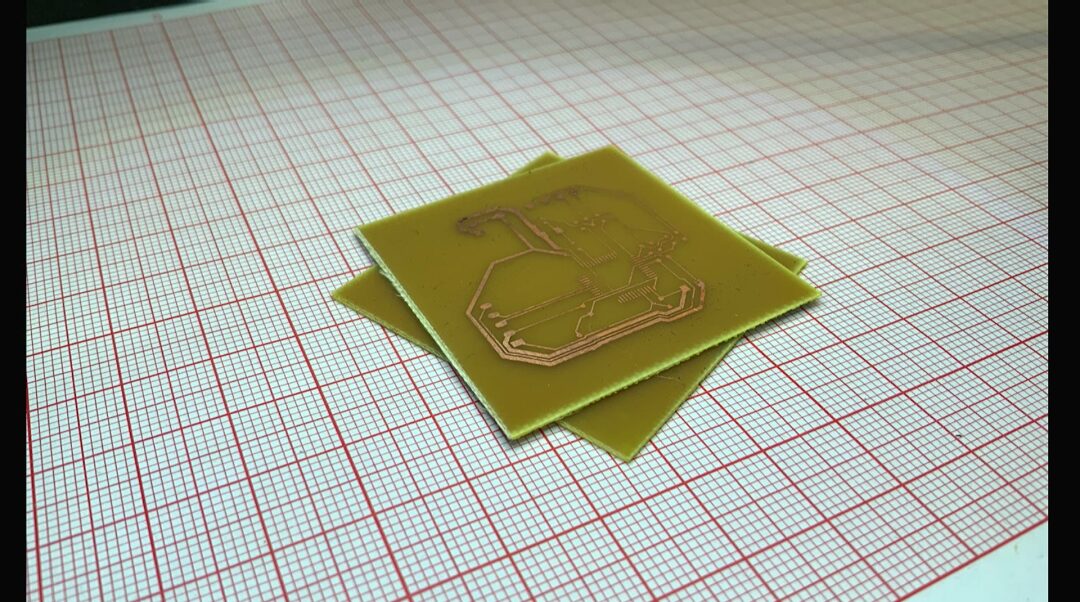
▲ Figure 1.2.2 PCB LayoutAfter one minute, two test PCB circuit boards were obtained, one of which was slightly over-etched. The other board, which was more normal, was used for testing.
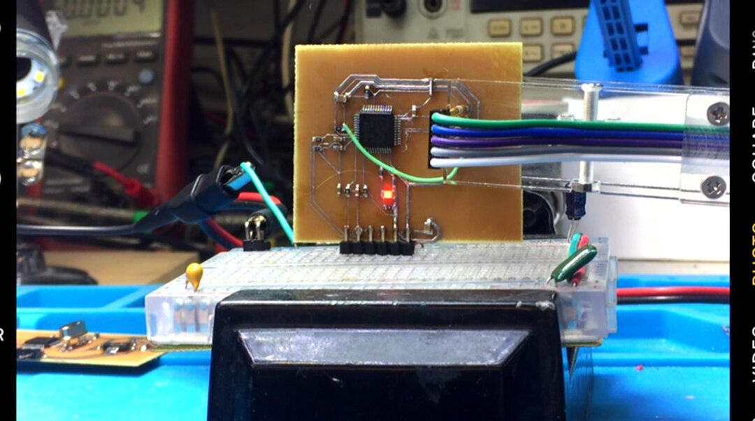
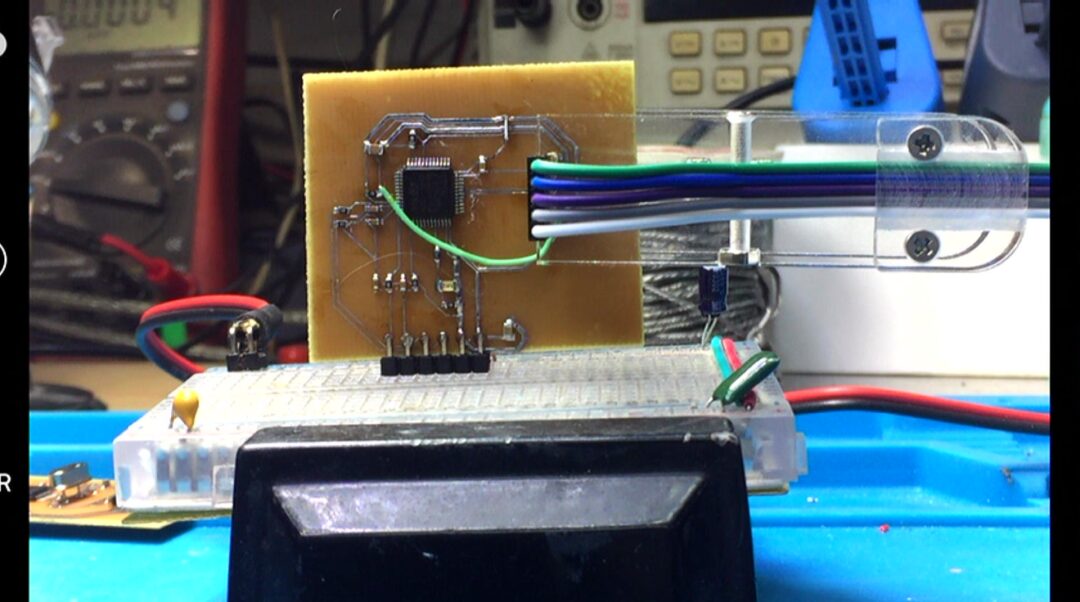
Soldering the circuit. It is placed on a breadboard for testing. The breadboard directly provides a 3.3V power supply to the test circuit. The program is downloaded via probe clips.
3. Software Testing
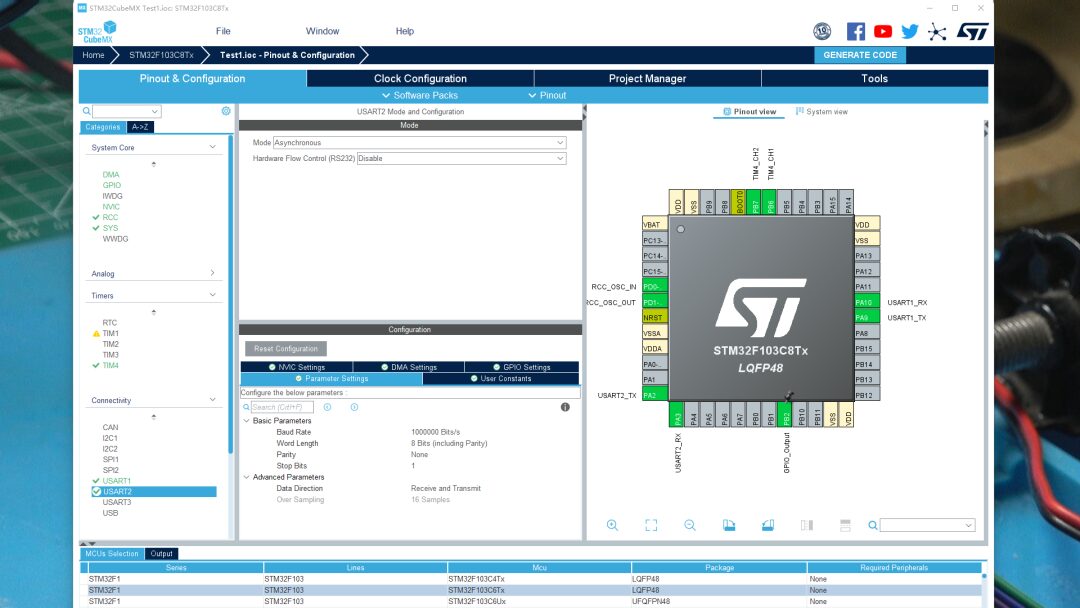
Set the basic parameters of the microcontroller’s UART2. The output baud rate is set to 1MHz. This can improve the update rate of the output signal. Through the oscilloscope, the time for each bit of the output signal is measured to be 1 microsecond, corresponding to a 1MHz baud rate. By enabling DMA output mode, UART2 can continuously send 32 bytes of content stored in memory through DMA.
D:\zhuoqing\window\ARM\IAR\STM32\Test\2024\Test1\Core\Src\main.c
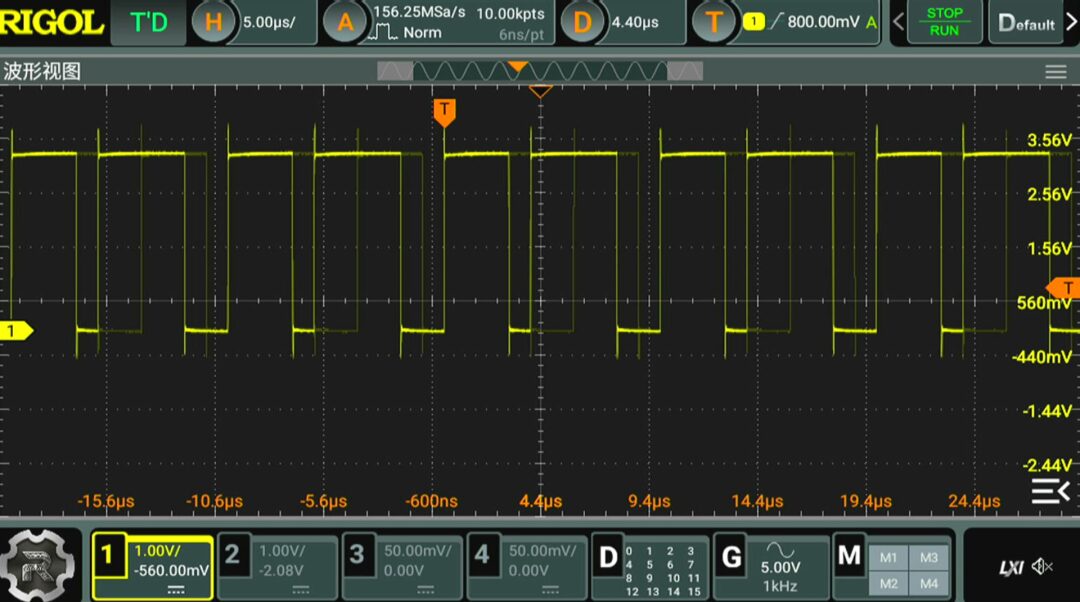
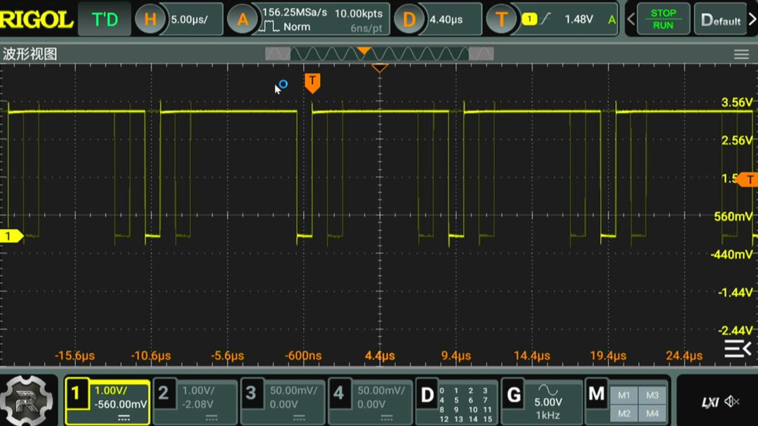
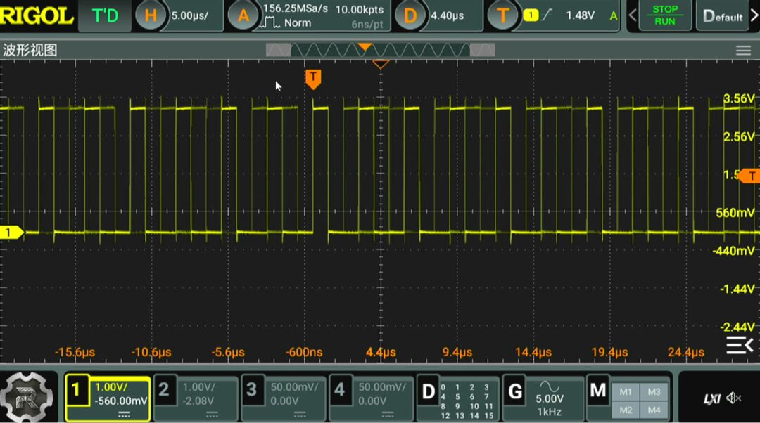
Setting 32 bytes to 0, the measured DC voltage after filtering the output voltage waveform is 0.326V. The pulses seen correspond to the high-level pulses of each byte’s stop bit. Setting all 32 bytes to 0xff, the low pulses correspond to each byte’s start bit, and the filtered DC voltage read is 2.9V. Setting 32 bytes to 0x55, alternating positive and negative pulse waveforms appear, with the filtered DC voltage being 1.61V.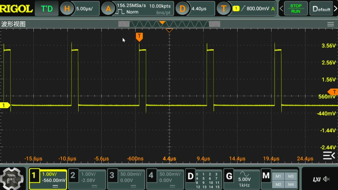
Next, we measure the filtered output DC voltage as the number of high-level bits in 32 bytes changes from 0 to 255. It can be seen that as the number of bits increases, the output DC voltage rises linearly. Due to the existence of start and stop bits in the UART sending bytes, the corresponding DC signal does not start from zero, and the highest level is not the maximum value of the output signal.
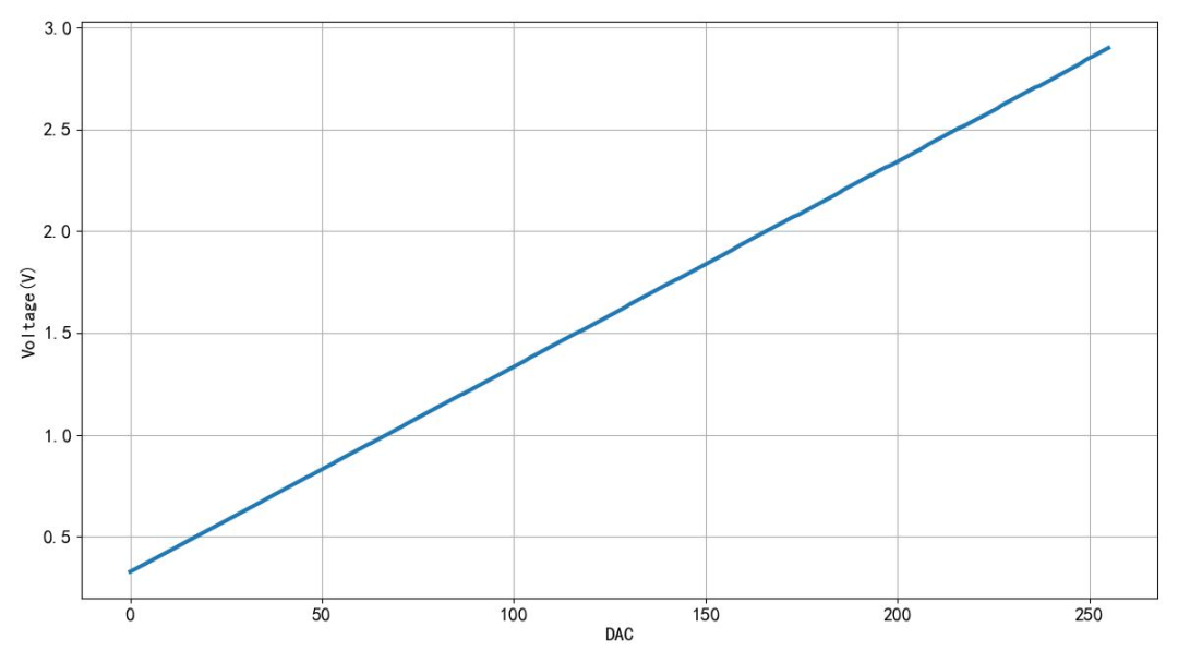
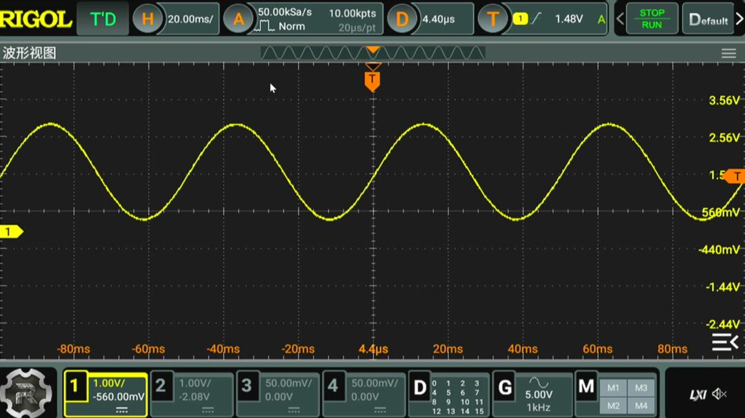
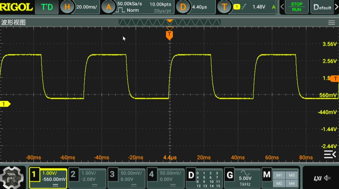
▲ Figure 1.3.1 Number of High-Level Bits in 32 Bytes and Filtered DC VoltageSetting the number of 1 bits in the 32 bytes of output DMA to vary according to a sine wave, the UART signal, after filtering, outputs a perfect sine waveform. When the output data is set to increase, the filtered waveform presents a sawtooth shape. A gradual change occurs on the falling edge due to the output RC low-pass filtering. This is the situation of outputting high and low levels; the RC low-pass filtering causes gradual changes on both the rising and falling edges.

※ Conclusion ※
This article tested the use of a microcontroller’s UART to output PWM waveforms, which after low-pass filtering, formed a DC voltage. This method can indeed provide a DAC port for the microcontroller in special circumstances.