This article is from the WeChat public account “Big Talk Imaging“, and the Zhihu column “All In Camera“. Please indicate the source when reprinting.
Big Talk Imaging reader QQ exchange group 2: 8332820006. Big Talk Imaging Technology Forum: www.dahuachengxiang.com
This site has new teaching videos “Image Sensor Technology and Applications” online on Taobao Education.
“Imaging System Image Quality Testing” “Imaging Algorithm Basics (Python Version)” “Imaging System Lens Optics” “New Version Image Quality Measurement and International Standards” “New Version CMOS Sensor Testing and International Standards” “New Version Digital Imaging System 42 Lecture” Course available at Big Talk Imaging Taobao Official Store:
https://shop3222456667.taobao.com/
Today, in-vehicle cameras have become an indispensable part of modern vehicles, whether in driver assistance or autonomous driving applications, with more and more cameras being equipped on vehicles.
According to Tesla’s current configuration, there are a total of 9 cameras in the vehicle.
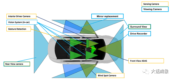
According to Waymo’s configuration, there are 29 cameras in the vehicle, with a total value exceeding 200,000 RMB.
To ensure that ADAS/autonomous driving can operate reliably, in-vehicle cameras must ensure stable and reliable image output that meets application requirements under various conditions, including day and night, weather conditions, lighting, and road conditions. This poses a challenging test for in-vehicle camera developers. It can be said that fully meeting the above requirements is an impossible task. Therefore, from the perspective of system development, to improve the robustness of the system, it is essential to analyze the possible failure modes of in-vehicle cameras. For each type of error, corresponding hardware and software countermeasures should be in place. Therefore, both ADAS and autonomous driving system developers will categorize and summarize the failure modes of in-vehicle cameras. During ML system training, failures can be introduced into the training model, and during product implementation, corresponding countermeasures can be formulated for each type of hazard. A research team funded by the European Road Safety Organization has compiled 20 common technical issues with in-vehicle cameras. While it is impossible to exhaustively cover all real scenarios, it will provide foundational help for software and systems engineers to establish resilient architectures and assess application robustness.
From the hardware perspective of in-vehicle cameras, failures may arise from 5 sources:
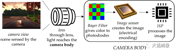
Lens, IR filter, Bayer Color Filter, Image Sensor, and ISP.
From the working environment of the camera, products like automobiles that operate in complex environments are affected by:
Weather (including wind, frost, rain, snow, temperature, etc.), lighting conditions, environmental pollution, time (day and night), geographical conditions, and regional usage differences.
Thus, all failures are the result of the combination of these 5 hardware components and the aforementioned usage conditions, reflected in the following failure images or abnormal electrical signal outputs.
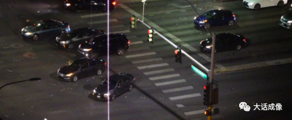
1. Banding, which may appear as vertical or horizontal stripes, generally caused by failures in the image sensor.
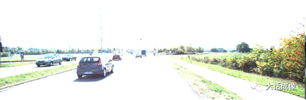
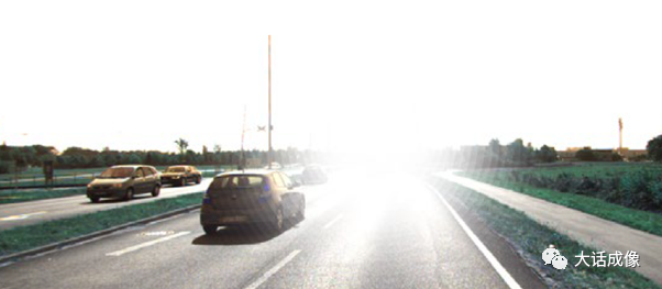
2. Image saturation, leading to loss of content information, generally caused by the image sensor, but may also originate from lens component failures.
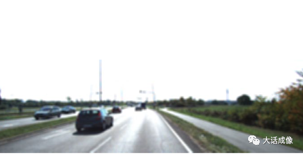
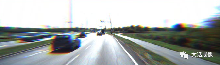
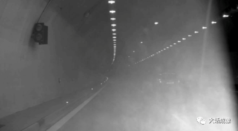
3. Blurriness, generally caused by lens damage or defocusing.
4. Bright lines, usually caused by opposing lidar illumination damaging the image sensor.
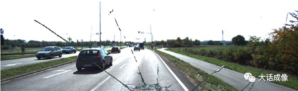
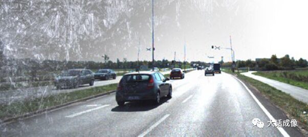
5. Lens damage, nothing much to say, a stone hit the lens.
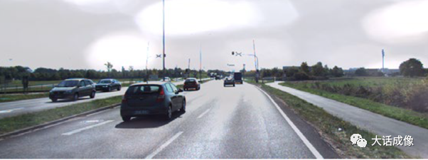
6. Condensation, where a large temperature difference between outside air and camera interior causes condensation on the lens, degrading image quality.
7. Bad pixels, image sensors are generally factory-calibrated for bad pixel elimination, but new bad pixels may develop over time, especially adjacent bad pixels, which cannot be dynamically eliminated by image signal processing.

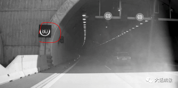
8. Dirt, where lens pollution from the environment leads to loss of image quality.
9. Glare, caused by light reflections within the lens or between the lens and image sensor.
10. Ice formation, where some cameras have heating functions to combat icing.
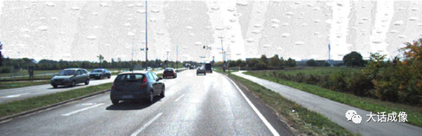
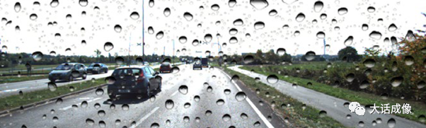
11. Rain, where raindrops interfere with image quality, and some cameras have air nozzles to blow water off the lens.
12. ISP color reproduction anomalies, caused by damage to the color filter or IR filter.

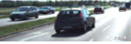
13. Color aberration correction errors, where color aberration appears at the edges of the image.
14. Demosaic not functioning, resulting in color loss in the image.

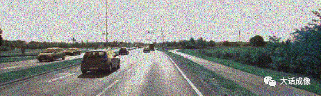
15. Noise reduction module anomalies, resulting in severe image noise.
16. Sharpening anomalies (also compounded by CA, etc.).
17. Electrical overload, where faults occur due to abnormal power supply or circuitry of the camera. These anomalies are generally classified in more detail in the image sensor’s Function safety section. Image sensor manufacturers categorize various types of anomalies based on design, such as clock, communication, bus, interface, and register read/write issues.
18. Damage caused by high temperatures, which often harms the lens and can also cause abnormal operation of the image sensor, such as dark current drift, spikes, etc.
19. LED flicker, caused by inconsistent power supply specifications of various LED lights; even with LFM image sensors, it cannot improve all LEDs.
20. Dust and sand can infiltrate the camera module, causing a decline in image quality.
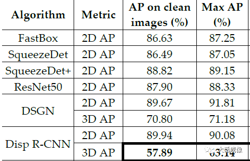
Based on these 20 common issues, researchers first analyzed the accuracy AP (average precision) measured by various convolutional neural networks under ideal conditions without issues.
Then, they analyzed the AP values of the system after introducing various fault interferences (lens damage, dirt, rain) to see how various networks cope with certain interferences.
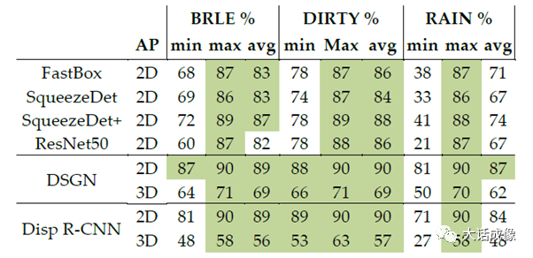
Developers can build their fault handling and response systems along this line to increase the stability of ADAS and autonomous driving systems.