This design is for a 16×16 LED electronic display screen. The entire system is centered around the 40-pin microcontroller AT89C51 produced by ATMEL, USA, and introduces the dynamic design and development process of the LED matrix electronic display screen controlled by this microcontroller. The chip controls two row drivers 74LS164 and two column drivers 74LS595 to drive the display screen. This electronic display can show various texts, characters, numbers, or monochrome images, capable of displaying one Chinese character on the full screen, composed of four 8×8 LED display modules to form a 16×16 matrix display mode. The display uses dynamic display techniques, allowing graphics or text to be shown in various ways such as static, scrolling in and out, etc. The article details the hardware design ideas for the LED matrix display, the functions and principles of each part of the hardware circuit, the corresponding software program design, and usage instructions.
1. Demonstration Video
2. Function Overview
This solution designs an electronic display screen with the following specific requirements: 1. The microcontroller must be a 51 microcontroller; 2. Display text, characters, and numbers through a 16×16 LED matrix; 3. Under visual conditions, the brightness of each point on the LED display must be uniform, sufficient, stable, and clear without crosstalk. 4. Text display includes: scrolling display, upward movement, leftward movement, downward movement, rightward movement, and static display.
3. Hardware Information
The overall block diagram of the LED matrix is shown in Figure 1. The matrix circuit can be roughly divided into three parts: the hardware of the microcontroller itself, the display driver circuit, and the control signal circuit. The control circuit includes a 51 CPU and some peripheral circuits. It is responsible for controlling the entire circuit and the operation of the corresponding program, sending commands to the display circuit. The matrix display body, as well as its row and column driver circuits. Since the two parts of the circuit can be placed together during board manufacturing, the character library can be placed in the control circuit to use serial communication to transmit data and commands to the display circuit. This display circuit uses a scanning method for display, with one row driver for each row, and the same name columns share a column driver. The row selection signal given by the row decoder starts scanning each row in order from the first row (connecting that row to one end of the power supply). On the other hand, based on the data latched in each column, it determines whether the corresponding column driver connects that column to the other end of the power supply. The connected columns will light up the corresponding LEDs at that row and column; the LEDs corresponding to the unconnected columns will be off.
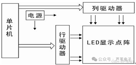 Figure 1 Overall Block Diagram of Matrix Display
 3.1 Microcontroller System and Peripheral Circuits
The microcontroller uses MSC-51 or its compatible series chips, with a 12MHz crystal oscillator to achieve a higher refresh rate for more stable display. The microcontroller’s serial port is connected to the column driver to display data. The lower three bits of port P2 are connected to the column driver 74LS595 to send out column selection signals; P2.3 and P2.4 are connected to the row driver 74LS164 to send out row selection signals. Ports P0 and P3 are left empty, which can be used to expand the system’s ROM and RAM or for key control when necessary. The minimum system of the microcontroller is shown in Figure 2.
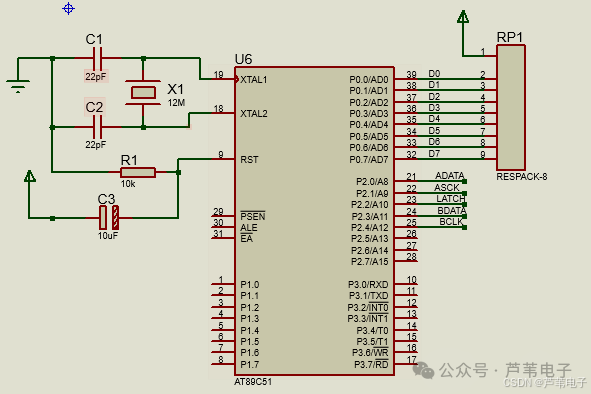 Figure 2 Minimum System of Microcontroller
3.2 Column Driver Circuit
The column driver circuit is composed of the integrated circuit 74LS595. It has an 8-bit serial-in parallel-out shift register and an 8-bit output latch structure, and the control of the shift register and output latch is independent, allowing for the display of the current row’s column data while transmitting the next row’s column data, achieving overlapping processing. The hardware connection of 595 is shown in Figure 3.
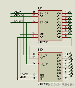 Figure 3 Hardware Connection Circuit of 74LS595
Introduction to 74LS595 PinsQ0–Q7: Eight parallel output terminals, can directly control the 8 segments of a digital tube.Q7′: Cascade output terminal. I connect it to the DS terminal of the next 595.DS: Serial data input terminal.(Pin 10): Low point usually clears the data of the shift register. I usually connect it to Vcc.(Pin 11): On the rising edge, the data of the data register shifts. Q0–>Q1–>Q2–>…–>Q7; on the falling edge, the data of the shift register remains unchanged. (Pulse width: for 5V, greater than several tens of nanoseconds is sufficient. I usually choose microsecond level).(Pin 12): On the rising edge, the data of the shift register enters the data storage register; on the falling edge, the data of the storage register remains unchanged. I usually keep RCK low, and after shifting is complete, generate a positive pulse at the RCK terminal (for 5V, greater than several tens of nanoseconds is sufficient. I usually choose microsecond level) to update the display data.(Pin 13): When high, output is disabled (high impedance state). If the microcontroller’s pins are not tight, using one pin to control it can conveniently produce blinking and extinguishing effects, which is more time-saving and labor-saving than controlling through the data terminal.
3.3 Row Driver Circuit
The row driver circuit is composed of the integrated circuit 74LS164. It has an 8-bit serial-in parallel-out shift register structure, allowing for the display of the current row’s column data while transmitting the next row’s column data, achieving overlapping processing. The hardware connection of 164 is shown in Figure 4.
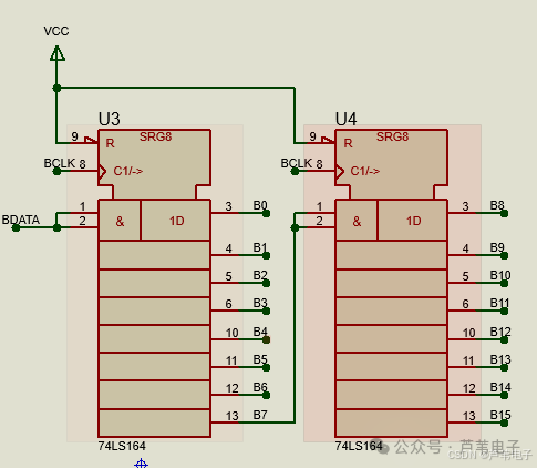 Figure 4 Hardware Connection Circuit of 74LS164
74LS164 is an 8-bit serial input, parallel output shift register, belonging to the TTL logic family. Its core function is to convert serial data into parallel output, suitable for digital systems that require I/O port expansion. Controlled by a clock signal (CLK), it receives serial data bit by bit (DATA pin input), and finally synchronously outputs on 8 parallel output terminals (Q0-Q7). Operating voltage: 5V (standard TTL level) maximum clock frequency: 25MHz driving capability: maximum 8mA sinking current per pin.
4. Program Design
Functionality: Move left and rightFunction input: dir for direction control 1 for left move 0 for right move*ptr for the content to be displayedn is the number of Chinese characters to movespeed is the moving speed
/*****************************************************************
*Functionality: Move left and right
*Function input: dir for direction control 1 for left move 0 for right move
           *ptr for the content to be displayed
           n is the number of Chinese characters to move
           speed is the moving speed
*****************************************************************/
void xmove(uchar dir, uchar *ptr, uchar n, uchar speed)
{
    uchar  i=0,  ib=0;
    uint   tmp=0, speedm=0;
    uchar  buffer2[16];         // Buffer for half a Chinese character

    n*=2;     // Left half and right half, so multiply by 2
    for(i=0;i<16;i++)   // Clear
        buffer2[i]=0;

    if(dir == 1)
    {/
/****     Move left    ****/
        for(n;n>0;n--)
        {
            if(ptr != 0)
            {
                tmp = n%2;    // Determine if it is the left half or right half
                for(i=0;i<16;i++)
                    buffer2[i]=ptr[i*2+tmp];

                if(tmp)        // When tmp is 1, point the address to the next Chinese character
                    ptr+=32;
            }

            for(tmp=8;tmp>0;tmp--)  // Move 8 columns
            {
                ib=0;
                for(i=0;i<16;i++)
                {                // Move 16 rows, a total of 16 bytes

                    buffer[ib] <<=1; // Move the first half
                    if(buffer[ib+1] & 0x80)
                        buffer[ib]++;
                    ib++;

                    buffer[ib]<<=1;            // Move the second half
                    if(buffer2[i] & 0x80)
                        buffer[ib]++;
                    ib++;

                    buffer2[i]<<=1;        // Buffer left half moves left by one
                }

                speedm=speed;    // Update matrix
                while(speedm--)
                    display();
            }
        }
    }
//--------------------------------------------------//
    else
    {
   /******  Move right   ******/
        for(n;n>0;n--)
        {
            if(ptr != 0)
            {
                tmp = (n+1) % 2  ;    // Determine left half or right half
                for(i=0;i<16;i++)
                    buffer2[i]=ptr[i*2+tmp];

                if(tmp == 0)        // When tmp is 0, point the address to the next Chinese character
                    ptr+=32;
            }

            for(tmp=8;tmp>0;tmp--)  // Move 8 columns
            {
                ib=0;
                for(i=0;i<16;i++)
                {                // Move 16 rows, a total of 16 bytes

                    buffer[ib+1] >>= 1;         // Move the second half
                    if(buffer[ib] & 0x01)
                        buffer[ib+1] |=0x80 ;

                    buffer[ib] >>= 1;        // Move the first half
                    if(buffer2[i] & 0x01)
                        buffer[ib] |= 0x80;
                    ib+=2;

                    buffer2[i] >>=1;        // The right half of the next Chinese character moves right by one
                }

                speedm=speed;
                while(speedm--)  // Update matrix
                    display();
            }
        }
    }

}
*Functionality: Move up and down*Function input: dir for direction control 1 for up move 0 for down move*ptr for the content to be displayedn is the number of Chinese characters to movespeed is the moving speed
/*****************************************************************
*Functionality: Move up and down
*Function input: dir for direction control 1 for up move 0 for down move
           *ptr for the content to be displayed
           n is the number of Chinese characters to move
           speed is the moving speed
*****************************************************************/
void ymove(uchar dir, uchar *ptr, uchar n, uchar speed)
{
    uchar i=0,  ib=0;
    uint  tmp=0, speedm=0;
char j=0;
    if(dir==0)
    {
   /****  Move down  ****/
        for(n;n>0;n--)
        {
            ib=31;
            for(i=16;i>0;i--)   // Move down 16 rows
            {
                for(j=29;j>-1;j--)
                    buffer[j+2]=buffer[j];    // Copy the content of the previous row to the next row

                if(ptr==0)
                {                // When moving empty, the first row of buffer is filled with 0
                    buffer[0]=0;
                    buffer[1]=0;
                }
                else
                {                // Otherwise, process the first row element of buffer
                        buffer[1]=ptr[ib];
                    buffer[0]=ptr[ib-1];
                    ib=ib-2;
                }
                speedm=speed;
                while(speedm--)      // Update matrix
                    display();
          }
            ptr+=32;
        }
    }

/****** Move up  *******/
    else
    {
        for(n;n>0;n--)
        {
            ib=0;      // Array element index
            for(i=0;i<16;i++)    // Move up 16 rows
            {
                for(j=0;j<30;j++)       // Copy the content of the next row to the previous row
                    buffer[j]=buffer[j+2];

                if(ptr==0)        // When moving in empty, the last row of buffer is filled with 0
                {
                    buffer[30]=0;
                    buffer[31]=0;
                }
                else
                {            // Otherwise, process the last row element of buffer
                    buffer[30]=ptr[ib];
                    buffer[31]=ptr[ib+1];
                    ib=ib+2;
                }
                speedm=speed;    // Update matrix

                while(speedm--)
                      display();
         }
             ptr+=32;
         }
  }

}
*Functionality: Scrolling display*Function input: *ptr for the content to be displayedn is the number of Chinese characters to movespeed is the moving speed
/*****************************************************************
*Functionality: Scrolling display
*Function input: *ptr for the content to be displayed
           n is the number of Chinese characters to move
           speed is the moving speed
*****************************************************************/
void jlmove(uchar *ptr, uchar n, uchar speed)        // Scrolling
{
    char i,j, k;
    uint speedm;

    for(k=0;k<32;k++)
    {
         buffer[k]=0;
    }
    for(n;n>0;n--)
    {
            for(i=0;i<32;i++)   // Scroll in 16 rows
            {
                buffer[i]=ptr[i];
                i++;
                buffer[i]=ptr[i];

                speedm=speed;
                while(speedm--)      // Update matrix
                    display();
            }
        displaytime(100);
    /****** Scroll out  ******/
            for(j=32;i>1;i--)    // Scroll out 16 rows
            {
                buffer[j-1]=0;
                j--;
                buffer[j-1]=0;

                speedm=speed;    // Update matrix
                while(speedm--)
                    display();
               }
               ptr+=32;
        }
}
5. Program Modification Instructions
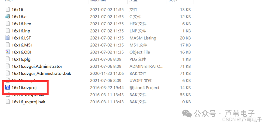
1. Open the program, double-click
2. Program modification
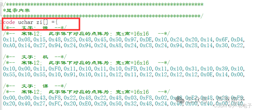
The above image shows the character library array, where the characters to be displayed can be modified. Modifying the characters requires the use of character library software, which can be opened by double-clicking zimo221.exe in the “Character Library Software” folder.

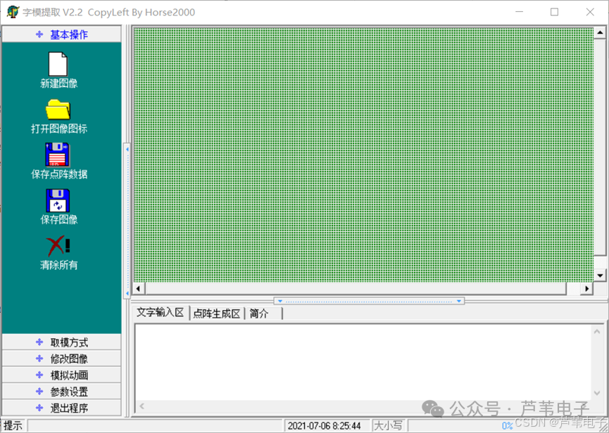
The software interface is shown in the following image:
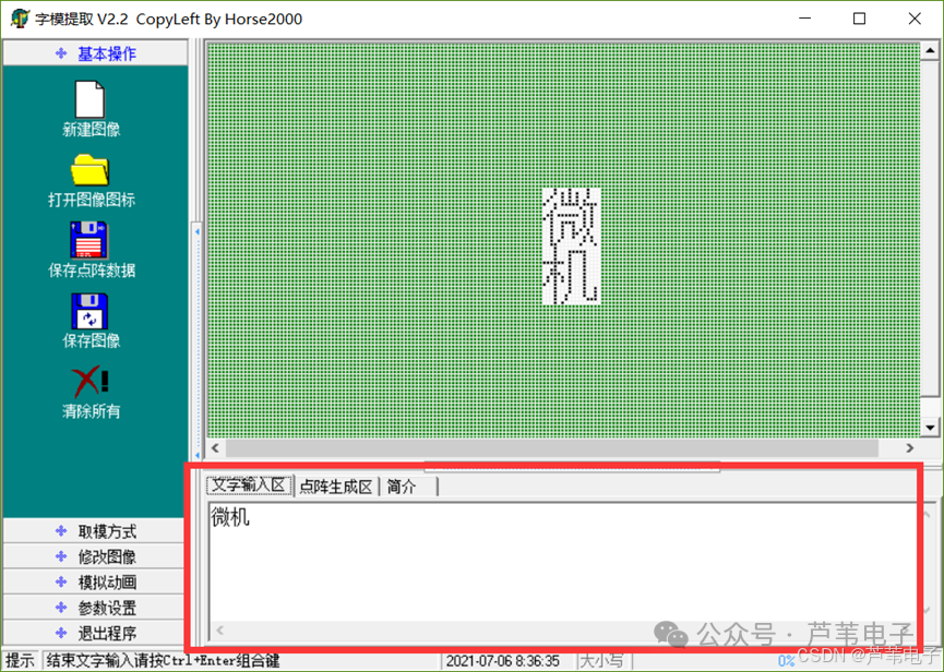
In the text input area, enter the text you want to modify. After entering the text, please press the Ctrl+Enter key combination. The following image takes “微机” (microcomputer) as an example.
Then click on the “Character Extraction Method” on the left sidebar, and then click on “C51 Format” to generate the 16×16 matrix character data for “微机” (microcomputer), as shown in the following image:
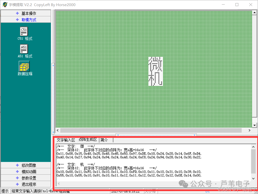
Copy the 16×16 matrix character data into the program’s “zi” array.
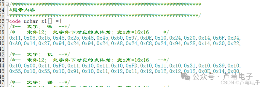
Note: Add 32 blank data (0x00) at the end of the “zi” array to leave a space for one character during the loop display (1 character has 32 data).

The following image shows the modifications for dynamic display;
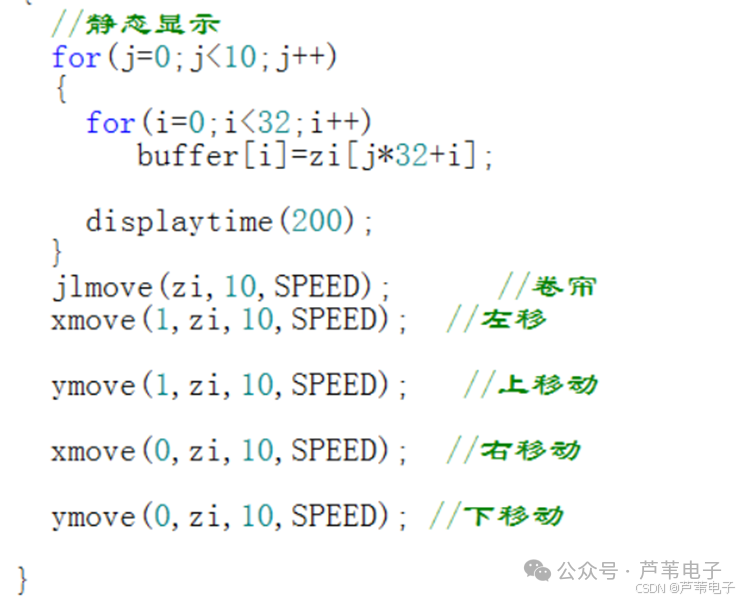
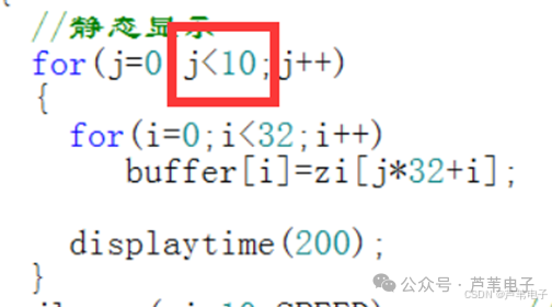
The display includes: static display, scrolling, left move, right move, up move, and down move display.Static display: Static display requires modifying the loop condition in the for loop to the number of characters in the “zi” array (1 character has 32 data), including blank characters.
Scrolling display: The three parameters of the jlmove function are: “zi” is the array to be scrolled, 10 is the number of characters in the “zi” array (including blank characters), SPEED is the display speed,

Modify SPEED as shown in the image
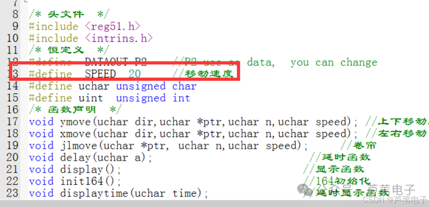
Left and right movement:Xmove (1, zi,10,SPEED) moves the font from left to right, changing 1 to 0 moves the font from right to left, “zi” is the array to be displayed, 10 is the number of characters in the “zi” array (including blank characters), SPEED is the display speed.Up and down movement:Ymove(1,zi,10,SPEED) moves the font from bottom to top, similarly changing 1 to 0 moves the font from top to bottom.Compile the program,
To obtain information: Follow the public account and reply with 0001