Bidirectional IO Port Output: Complementary Push-Pull
In the 51 microcontroller, the P0 port operates in standard IO mode as a quasi-bidirectional IO port. When in the second functional state, it becomes a standard bidirectional IO port. Due to the output requirements of bidirectional IO ports needing to output high and low levels, complementary push-pull circuits are typically used.
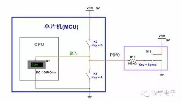
In the second functional state, the P0 port of the 51 microcontroller uses a complementary push-pull output method. What is complementary push-pull? Below is its equivalent circuit diagram.
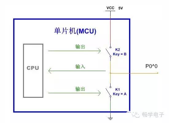
When the P0 second function is used as output, switches K1 and K2 alternately open. When K2 closes and K1 opens, a high level is output, and its driving capability is very large because the resistance of the electronic switch is small (unlike the higher value of a pull-up resistor). Conversely, when K2 opens and K1 closes, a low level is output.
The two switches alternate conduction, complementing each other; “pull” means “to push”. The two electronic switches are responsible for “pushing” and “pulling” current at the IO port output, hence the term complementary push-pull.
This structure of the IO port has obvious advantages: strong driving capability and stable reliability. The downside is that it is relatively difficult to implement. During the switching process of output levels, for example, switching from low to high, when K1 disconnects, it requires a quick high level output, meaning K2 should close immediately; simultaneously, if K1 has not yet opened, and K2 closes prematurely, it would be equivalent to both switches conducting at the same time, leading to a direct short circuit, which would have serious consequences. Therefore, circuit control is needed to ensure the coordinated operation of the two switches.
Bidirectional IO Port Input: High Impedance State, Input Resistance
The output of a bidirectional IO port only requires the ability to output high and low levels, so it is not necessary to use a complementary push-pull circuit. However, the advantage of using a complementary push-pull circuit is that it can simultaneously achieve high impedance state input, thus realizing a standard bidirectional IO port.
When both K1 and K2 in the diagram are disconnected, the IO port can operate in a high impedance state. What exactly is a high impedance state?
When the IO port is in a high impedance state, it is also referred to as a floating input state, where its level is indeterminate, neither high nor low. We can imagine that when the microcontroller detects the high or low level of the IO port, it is akin to having a voltmeter inside the CPU, and this voltmeter has a very high internal resistance, such as the 100MΩ given in the diagram. Here, we can refer to this voltmeter’s internal resistance as the input resistance of the P0.0 port at this time (it can also be approximated as output impedance; resistance is for DC, while impedance is for AC. This is knowledge from analog circuits, which will not be elaborated here).
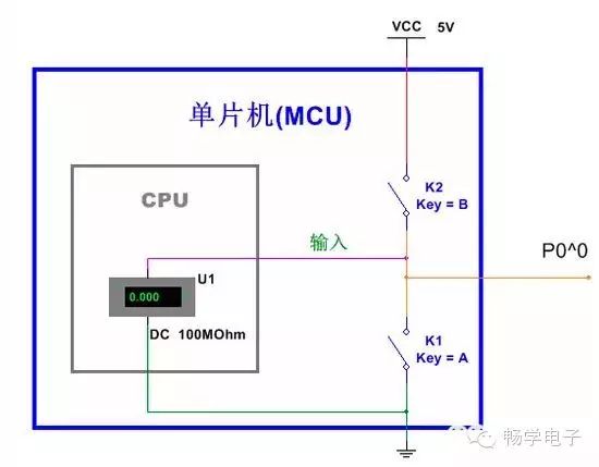
Now, imagine if you accidentally touched the P0.0 port with your hand, and since the human body itself is a conductor with a high resistance, coupled with various electromagnetic interference around, there may be some very weak current on your hand. At this time, the voltmeter’s reading would change, and the level read by the microcontroller would also change. The result of the high impedance state is that even very small external interference can cause a change in the level read, and even if the IO port is not touched, the reading may still vary each time due to external electromagnetic waves interfering with the IO port. Later, we will use the 51 microcontroller to conduct an experiment to experience the high impedance state of the P0 port.
Significance of High Impedance State, Output Resistance
Why is it required to have a high impedance state when inputting to a bidirectional IO port?
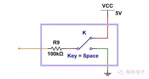
We assume that there is a device, with the equivalent circuit as shown in the diagram below. The switch toggles up and down, outputting high and low levels, which can be detected through a voltmeter. However, its driving capability is very weak, unable to even drive an LED. The 100kΩ inside the device can be referred to as the output resistance of the device (it can also be approximated as output impedance).
Let this device output a low level, and then connect it to the P1.0 port of the 51 microcontroller. At this time, VCC passes through the 10kΩ pull-up resistor to reach the IO port, then to the internal 100kΩ resistor of the device, and through switch K to GND. According to the voltage divider principle, the voltage value on P1.0 is approximately 4.55V, thus the microcontroller reads it as a high level. However, in reality, the device wants to output a low level to inform the 51 microcontroller. Here, the microcontroller pin, functioning as an input, interferes with the external device’s output value, effectively causing the microcontroller’s IO port to also output.
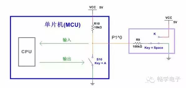
When the P0 port of the microcontroller operates in the second function input state, or in the ordinary IO port input state without external pull-up or pull-down resistors, both internal electronic switches are disconnected, presenting a high impedance state to the outside. From the diagram, it can be seen that the output level from the device can be accurately read by the microcontroller. The reason for accurate reading is that the output resistance of the device is smaller than the input resistance of the microcontroller’s IO port.
Some may argue that if the resistance in the device is changed to 1000MΩ, then the microcontroller would not be able to read the level accurately. However, generally, we do not need to consider such extremes. In an ideal high impedance state, its input impedance should be infinite, which is somewhat special like a superconductor. Generally, it is assumed that the resistance of wires is almost 0, and similarly, the input resistance in a high impedance state is considered to be infinite.
In summary, in high impedance states, the input resistance of the IO port is very large, making it less likely to interfere with the output levels from devices with larger output resistances and weaker driving capabilities.