MIPI (Mobile Industry Processor Interface) is a core transmission standard for devices such as smartphones, tablets, and automotive systems, which includesD-PHY (used for CSI cameras/DSI displays) andC-PHY (higher bandwidth, no independent clock) physical layer protocols. Its characteristics include:
- Differential Signals: D-PHY includes 1 pair of clock + 1~4 pairs of data lines; C-PHY transmits embedded clock using a three-wire system.
- High-Frequency Characteristics: D-PHY rates reach 2.5Gbps, while C-PHY can reach 5.7Gbps, making them extremely sensitive to impedance and timing.
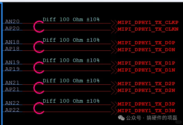
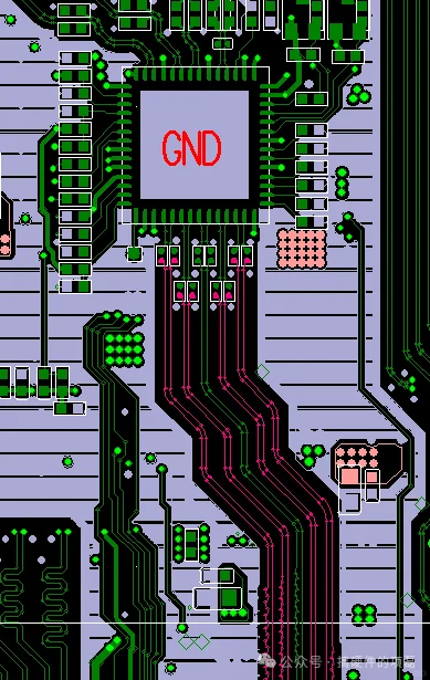
Core Principles of PCB Layout: Avoiding Interference from the Source
-
Proximity Layout of Components
- The distance between the main control chip and the MIPI interface (such as camera/display connectors) should be≤50mm, minimizing high-speed path length.
- Place interfaces near the board edge to avoid impedance changes caused by FPC bending.
Segmentation and Isolation
- Keep away from interference sources such as power modules, RF antennas, and crystal oscillators (spacing ≥ 3 times the line width).
- Decoupling capacitors should be placed close to connector pins (preferably on the bottom layer) to reduce power supply noise.
Summarized as the following 8 key points.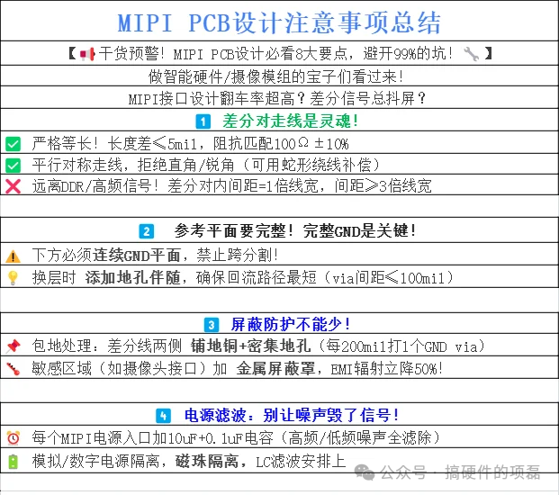
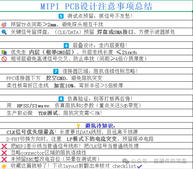
- 、
| Parameter | D-PHY Requirements | C-PHY Requirements |
|---|---|---|
| Length Mismatch of Differential Pairs | ≤5mil | ≤6mil (within TRIO group) |
| Inter-group Length Mismatch | ≤100mil | ≤100mil |
| Clock-Data Mismatch | ≤12mil | No independent clock |
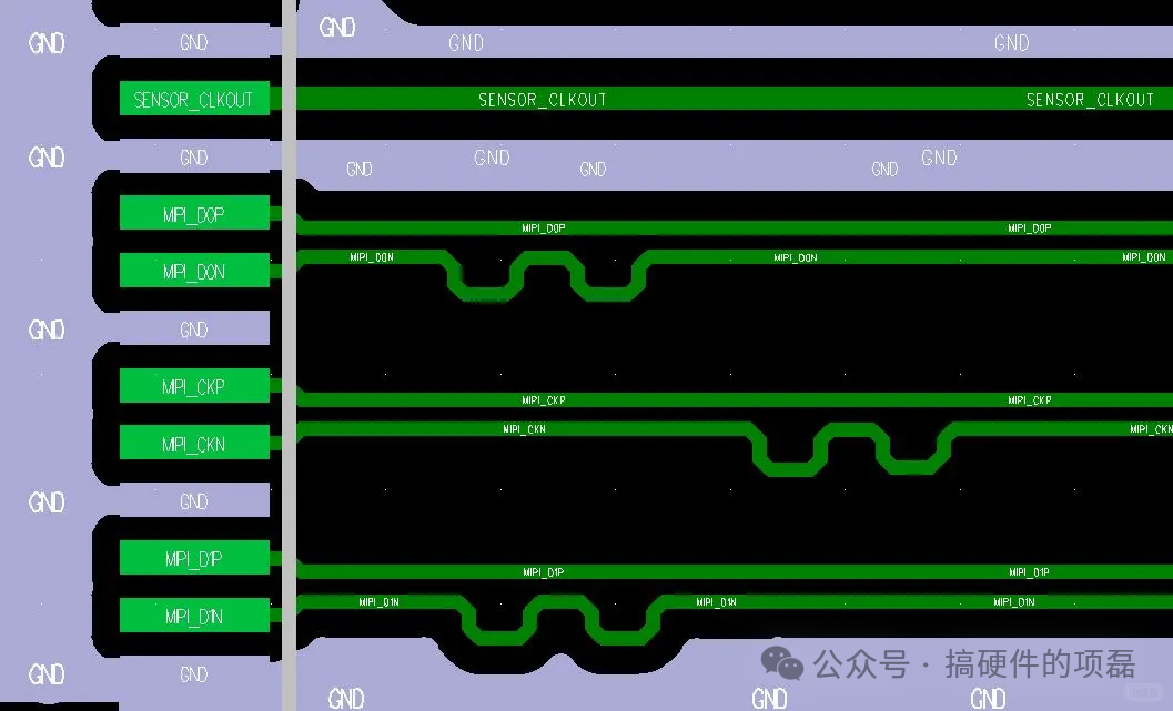
Appendix: MIPI Design Checklist
- Impedance 100Ω±10%? ✅
- Length difference ≤5mil? ✅
- Maximum of 2 vias with accompanying ground vias? ✅
- Continuous reference GND without segmentation? ✅
- 3W spacing + isolation from interference sources? ✅
- Share and save immediately to help the team avoid pitfalls in high-speed design!