Click the aboveblue to follow our public account and set it as a star⭐, so you can see the latest content first。
 The low-voltage dual-core architecture of the XiaoYao dual-core battery draws on the dual-engine redundancy design in the aviation field (such as the Boeing 787), dividing the low-voltage power supply system into two independent and mutually backup “energy zones”. When one area experiences a fault that causes a 12V power interruption, the intelligent management system (BMS) can switch to the backup energy zone within milliseconds, ensuring the continuous operation of critical low-voltage systems such as body control, lighting, and power steering.
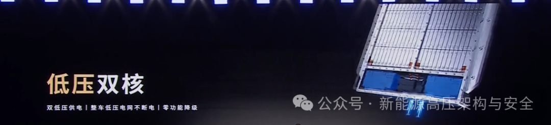
In the previous issue on high-voltage dual-core, it was mentioned that the main energy zone (such as ternary batteries) is responsible for daily commuting, while the range-extending energy zone (such as lithium iron phosphate self-generating negative electrode batteries) provides long-range support, achieving “electric-electric range extension” through intelligent distribution strategies. This involves the need for algorithms to further harmonize the voltage platforms of two different chemical systems at the low-voltage BMS control level.
Specifically, there are two issues that need to be addressed:
1. Vehicle high-voltage platform matching: Traditional single-type battery packs are limited in performance or incur high costs due to mismatches between voltage characteristics and electrical system requirements. For example, sodium-ion batteries have a wide voltage range (1.5-4.2V), and when grouped, exceed the vehicle’s high-voltage system (200-480V) requirements, necessitating voltage adjustment through mixing with other batteries.
2. SOC estimation of dual-system battery cells: The OCV-SOC curve of lithium iron phosphate batteries is exceptionally flat, typically a certain open-circuit voltage (OCV) value can be mapped to a wide range of state of charge (SOC) values. This makes it difficult to accurately estimate the SOC of lithium iron phosphate batteries.
To address these two issues, we will look at how some patents from NIO and CATL solve these problems.
High Voltage Platform Matching of Dual-Core Batteries
1. Vehicle Voltage Platform Matching Requirements
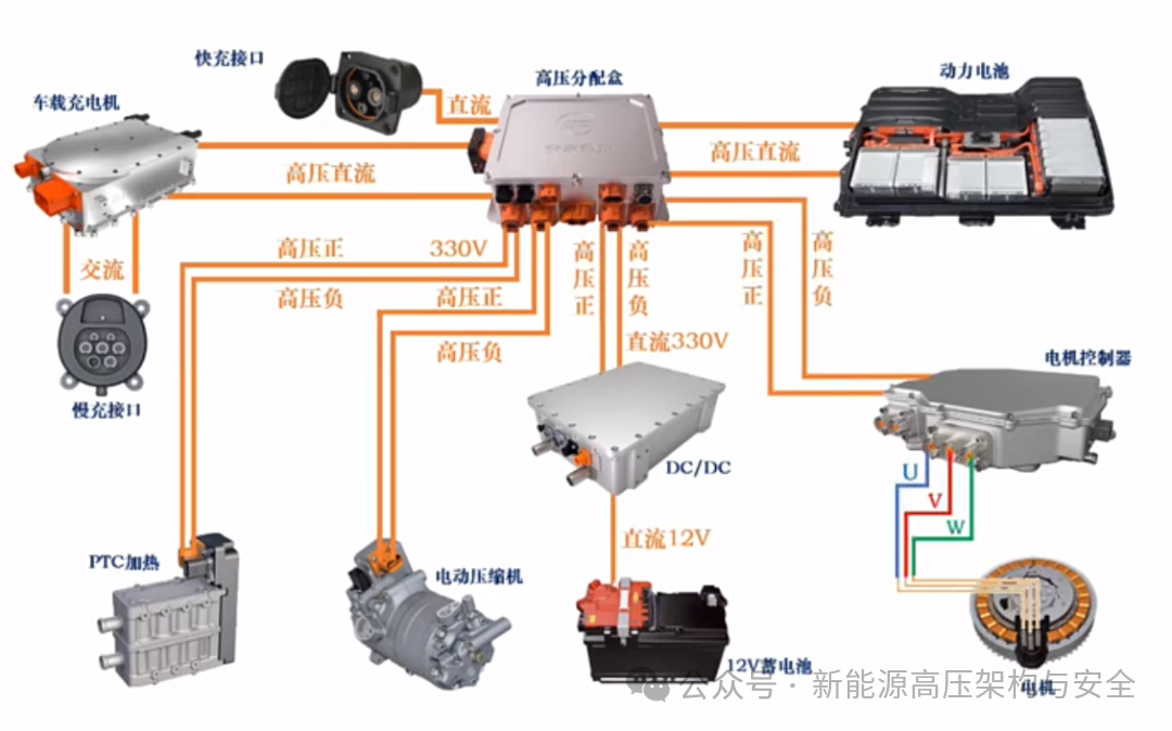
The operating voltage range of the vehicle’s high-voltage electrical system is too wide, which affects the performance and efficiency of high-voltage electrical subsystems such as motor controllers, PTC heaters, drive motors, air conditioning compressors, and onboard chargers (OBC), posing challenges for the overall vehicle matching design. Taking the current mainstream passenger 400V voltage platform as an example, the typical operating voltage range of the matched high-voltage system is about 200 to 480V.
For example, the output voltage range of a sodium-ion battery pack formed by connecting 120 individual open-circuit voltage range 1.5V to 4.2V sodium-ion batteries in series (120S series) is approximately 180V to 530V, where the ranges of 180V to 200V and 480V to 530V may cause abnormal operation of the vehicle’s high-voltage electrical system, leading to limited performance of the vehicle’s electrical system, or wasting part of the available SOC of the sodium-ion battery pack.

2. CATL’s Approach
Unlike sodium-ion batteries, the output voltage range of a 120S series ternary lithium battery pack is approximately 300V to 420V, while the output voltage range of a 120S series lithium iron phosphate battery is approximately 360V to 470V. Both of these ranges are narrower than that of sodium-ion battery packs and also smaller than the operating voltage range required by the vehicle’s high-voltage system. Therefore, using sodium-ion batteries in combination with lithium iron phosphate and/or ternary lithium batteries, can both reduce the cost of the mixed battery pack and ensure that the output voltage range of the mixed battery pack matches the requirements of the vehicle’s high-voltage electrical system.
Here we will analyze a patent from CATL regarding the architecture of mixed battery packs to discuss its implementation scheme:
3. Mixed Battery Pack Architecture
Composition: At least two types of batteries (such as sodium-ion batteries + lithium iron phosphate/ternary lithium batteries) are used to complement each other’s different voltage characteristics.
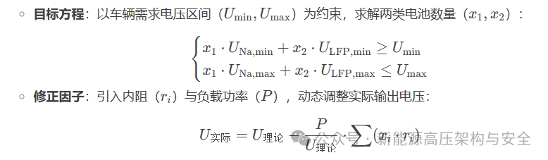
Objective: By adjusting the number of batteries, the output voltage range of the mixed group (corrected voltage range) becomes a subset of the electrical system’s operating voltage range.
Core Formula:
4. Implementation Steps
Step 1: Parameter Matching
Input: Target voltage range (e.g., 200-480V), battery cell OCV curve, internal resistance, target total energy (E).
Output: Combination of sodium and lithium iron phosphate battery quantities (e.g., 60 series Na + 60 series LFP).
Step 2: Numerical Solution Optimization
Solve the equations for non-integer solutions, round off, and combine energy constraints to filter the optimal combination.
Step 3: Dynamic Correction
SOC Calibration: To address the differences in OCV curves between sodium and lithium batteries, a multi-dimensional mapping table is constructed (as shown below), increasing the weight of sodium batteries at low temperatures.
Balancing Strategy:
Passive Balancing: When there is a small voltage difference, balance by dissipating energy through resistors.
Active Balancing: When there is a large capacity difference, use inductors/capacitors to transfer energy across modules (e.g., supplementing energy from healthy sodium battery areas to aging lithium iron phosphate areas).
5. Hardware and Layout Design
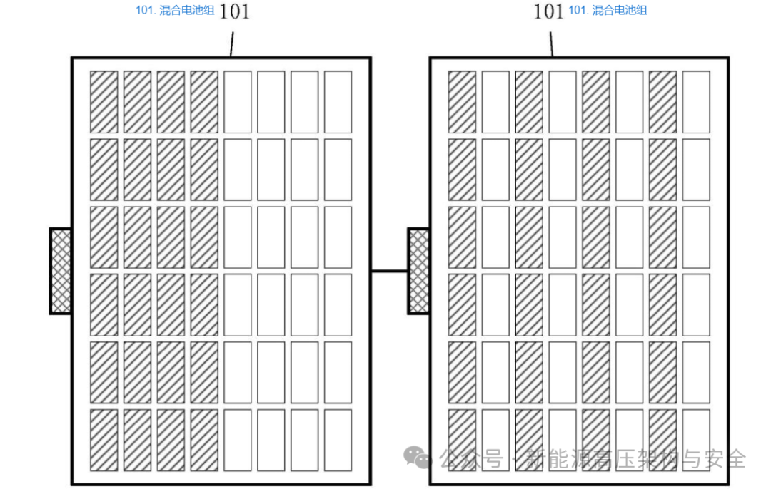
Physical Structure: (as shown below):
Interleaved Arrangement: Batteries of the same type are arranged in rows, aligned in size (e.g., height, polarity), facilitating BMS collection and management.
Regional Layout: Sodium batteries and lithium iron phosphate batteries are arranged in separate zones, supporting independent thermal management (e.g., enhanced cooling for sodium battery areas).
The thermal management scheme adopts dual-branch cooling:
Low-temperature scenarios: The outer branch circulates hot water for insulation, preventing performance degradation of sodium batteries.
High-temperature scenarios: The inner branch circulates cold water for cooling, prioritizing cooling of high-rate areas (e.g., ternary lithium cells).
6. Application Effect Analysis
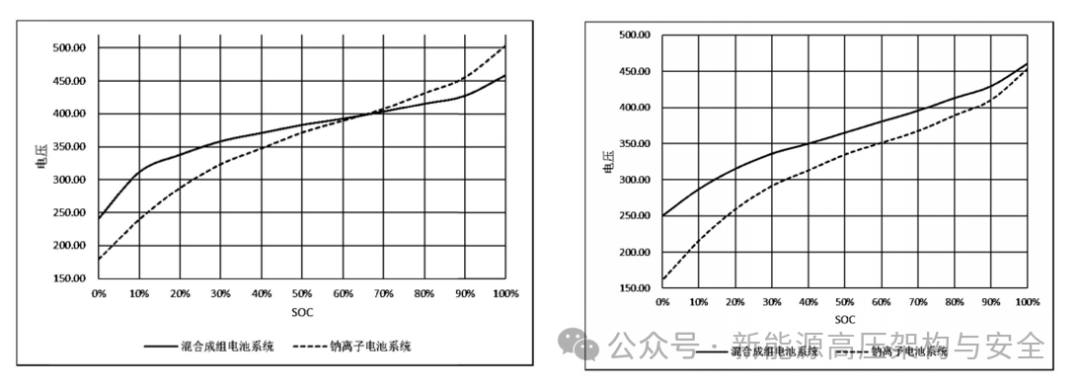
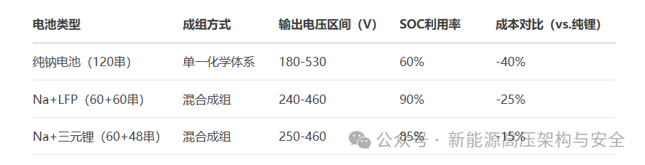
Electric Vehicles: The mixed sodium-ion and lithium iron phosphate battery (1:1) can narrow the output voltage from 180-530V to 240-460V.
Multi-Battery Pack Systems: In commercial/passenger vehicles, multiple independent battery packs can be connected in series/parallel, supporting flexible combinations.
7. Technical Advantages of CATL’s Solution
Enhanced Compatibility: The mixed solution allows sodium-ion batteries to adapt to existing high-voltage systems without the need to modify electrical equipment.
Cost Optimization: Increasing the proportion of sodium batteries (e.g., 60 series sodium + 48 series ternary lithium), reduces dependence on lithium resources by 30%.
Full Lifecycle Management: Dynamic balancing algorithms mitigate differences in battery degradation, enhancing cycle life.
Thermal Safety: The dual-branch cooling system controls temperature in zones, preventing local thermal runaway.
The SOC estimation challenge of lithium iron phosphate + ternary batteries
1. Battery System Technical Background:
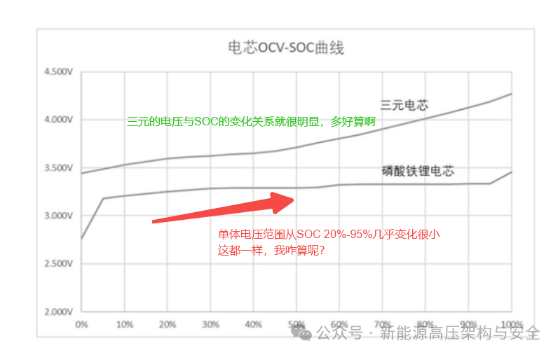
Lithium Iron Phosphate (LFP): Good safety, but the “voltage – charge curve” is too flat (for example, the voltage changes little when the charge drops from 20% to 10%), making it difficult to judge the remaining charge based on voltage, which is a well-known industry challenge.
Ternary System (NCM): The OCV-SOC curve has a steep slope, allowing OCV to accurately map to SOC, resulting in high estimation accuracy.
Therefore, currently, due to the curve characteristics of a single LFP battery system, it is impossible to accurately estimate SOC, necessitating the combination of the advantages of dual-system batteries. We hope to have the two types of batteries “team up”, using the “charge calculation advantage” of ternary batteries to accurately estimate the charge of the entire battery system while retaining the safety of lithium iron phosphate.
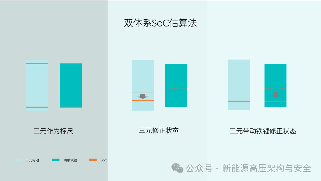
2. Core Method: Ternary Battery as a Reference
Here, we will explain how this ternary reference is used in a patent from NIO. (It must be said that NIO is indeed the first to explore many new technologies in the electric field, daring to think and act, a thumbs up!)
First, the entire battery system includes the first system battery (such as lithium iron phosphate LFP) and the second system battery (such as ternary NCM).
The overall scheme is to map the upper and lower limits of the state of charge (SOC) of the second system battery to the SOC range of the battery system, establishing a mapping relationship, and then estimating the overall SOC of the battery system based on the SOC of the second system battery;
while dynamically adjusting the SOC ranges of the two system batteries, such as setting the lower limit of the SOC of the first system battery below that of the second system, the upper limit of the second system above that of the first system, or opening and supplementing ranges, etc., to cope with battery degradation and solve the SOC estimation problem of lithium iron phosphate batteries due to the flat OCV-SOC curve, achieving accurate estimation of the battery system’s state of charge.
Patent Description:
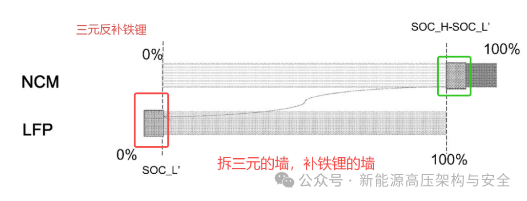
① The lower limit of the ternary system battery NCM is maintained as the empty point of the battery system (0%) and the corresponding state of charge of the lithium iron phosphate system battery LFP is referred to as SOC_L,
② The upper limit of the lithium iron phosphate system battery LFP is maintained as the full point of the battery system (100%) and the corresponding state of charge of the ternary system battery NCM is referred to as SOC_H.
Through this design, the state of charge range of the ternary system battery NCM is maintained from the empty point of the battery system (0%) to the full point (SOC_H), and to ensure the relative stability of the state of charge range (0%-SOC_H), the two state of charge ranges (0-SOC_L) and (SOC_H-100%) are reserved and used for dynamic adjustment of the state of charge range of the ternary system battery NCM when battery degradation occurs.
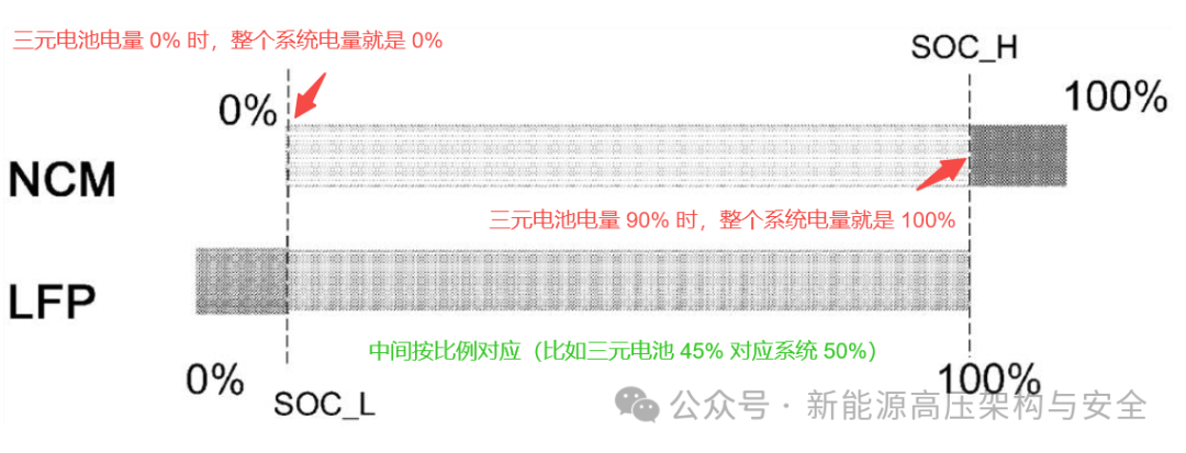
In this way, we can first calculate the charge of the ternary battery (because its voltage changes significantly, making it easy to calculate accurately), and then through the above “mapping relationship”, directly obtain the charge of the entire battery system.
3. Dynamic Adjustment: What to Do When Batteries Degrade Over Time?
Over time, battery capacity decreases (for example, originally able to store 100 degrees of electricity, after degradation can only store 90 degrees), and the degradation rates of the two types of batteries may differ. At this time, it is necessary to flexibly adjust their charge ranges to ensure that the ternary battery’s charge can always “represent” the entire system.
Basic Setting: Leave Sufficient “Buffer Range”
① Set the “minimum charge lower limit” of lithium iron phosphate lower than that of the ternary battery (for example, lithium iron phosphate can be used down to -5%, but actually stops at 0%, leaving a 5% buffer).
② Set the “maximum charge upper limit” of the ternary battery higher than that of lithium iron phosphate (for example, lithium iron phosphate is full at 100%, the ternary battery can charge to 105%, but actually only uses up to 100%, leaving a 5% buffer). This way, when both types of batteries degrade, there is extra range available for adjustment.
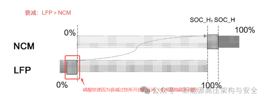
Situation 1: Lithium Iron Phosphate Degrades Faster (Capacity Drops More)
For example, lithium iron phosphate originally could be used from 0% to 100%, but after degradation can only be used up to 90% when full, causing the ternary battery’s “full charge point” to advance (for example, 90% of the ternary battery corresponds to 90% of the system, which is not enough for 100%).
Adjustment Method: Open up the lower limit range of lithium iron phosphate that has not been used (for example, the originally reserved -5% to 0%) to supplement the ternary battery, allowing the ternary battery’s 90% to correspond to the system’s 100%, maintaining accurate mapping.
Patent Description:
Since the first system battery, the lithium iron phosphate system battery LFP, degrades faster than the second system battery, the ternary system battery NCM (the lithium iron phosphate system battery LFP capacity degrades faster), the upper limit of the lithium iron phosphate system battery LFP (100%) is relatively lower than that of the ternary system battery NCM.
As shown in the figure below, the upper limit of the lithium iron phosphate system battery LFP corresponds to the SOC_H of the ternary system battery NCM, and SOC_H1 <SOC_H, which causes the state of charge range of the ternary system battery NCM to become 0-SOC_H1, which is a reduction compared to the original 0-SOC_H.
In order to keep the state of charge range of the ternary system battery NCM unchanged, the 0%-SOC_L charge capacity range of the lithium iron phosphate system battery LFP is gradually opened up, with the opened charge capacity being (SOC_H-SOC_H1) × weight, ensuring that the state of charge range of the ternary system battery NCM remains 0-SOC_H.
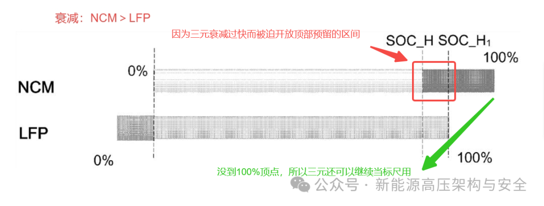
Situation 2: Ternary Battery Degrades Faster
For example, the ternary battery originally at 90% corresponds to 100% of the system, but after degradation may require 100% to correspond to 100% of the system.
Adjustment Method: Open the upper limit range of the ternary battery (for example, originally only using 90%, now using up to 100%), allowing its 100% to correspond to the system’s 100%, realigning the full charge point.
Patent Description:
The degradation of the ternary system battery NCM must be greater than that of the lithium iron phosphate system battery LFP, causing the full charge point of the lithium iron phosphate system battery LFP to shift upwards to correspond to the SOC_H of the ternary system battery NCM. As shown in the figure below, the full charge point of the lithium iron phosphate system battery LFP corresponds to the SOC_H1 of the ternary system battery NCM. In this case, gradually open the upper range of the ternary system battery NCM (SOC_H-SOC_H1) to align this range with the full charge point of LFP.
In this way, the state of charge range of the ternary system battery NCM can be maintained as (0%-SOC_H1), and based on the adjusted (0%-SOC_H1), the state of charge of the battery system can be estimated. Since the adjusted state of charge range of the ternary system battery NCM (0%-SOC_H1) still corresponds to the empty point to the full charge point of the battery system, it can accurately reflect the state of charge of the battery system.
Extreme Situation: The Buffer Range of Lithium Iron Phosphate is Exhausted
If the lower limit of lithium iron phosphate has already been used up to 0%, and cannot be lowered further, then appropriately lower the upper limit of the ternary battery (for example, from 90% to 85%), providing the freed range to lithium iron phosphate, ensuring that the charge ranges of both batteries always “connect” without estimation gaps.
Patent Description:
When the degradation of the lithium iron phosphate system battery LFP exceeds this threshold (0%-SOC_L), that is, when the lower limit range of the lithium iron phosphate system battery LFP has been fully opened and supplemented to the ternary system battery NCM, the state of charge lower limit of the ternary system battery NCM and the lithium iron phosphate system battery LFP becomes the same, that is, 0%.
In this case, the lithium iron phosphate system battery LFP will be emptied first, causing the state of charge of the ternary system battery NCM to no longer accurately reflect the empty point of the battery system. To ensure that the state of charge range of the ternary system battery NCM still accurately reflects the state of charge range of the battery system (empty point to full charge point), it is necessary to reverse supplement part of the state of charge capacity of the ternary system battery NCM to the lower limit range of the lithium iron phosphate system battery LFP.
Specifically, the upper limit of the ternary system battery NCM is set to (SOC_H-SOC_L’), where SOC_L’ is the corresponding percentage of SOC value of SOC_L converted from LFP capacity to NCM capacity. At the same time, the corresponding SOC_L’ of the ternary system battery NCM capacity is supplemented to the lithium iron phosphate system battery LFP.
With this adjustment, the upper limit of the ternary system battery NCM still corresponds to the full charge point of the battery system (which is also the full charge point of the lithium iron phosphate system battery LFP), and the lower limit still corresponds to the empty point of the ternary system battery NCM (which is also the empty point of the ternary system battery NCM). The adjusted state of charge range of the ternary system battery NCM (0%- (SOC_H-SOC_L’)) can still accurately reflect the state of charge of the battery system.
4. Advantages: What Problems Are Solved?
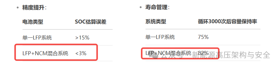
Accurate Calculation: By leveraging the “voltage sensitivity” of ternary batteries, we can avoid the “flat voltage” challenge of lithium iron phosphate, allowing the entire battery system’s charge display to be more accurate, reducing range anxiety.
Adaptation to Degradation: Regardless of which battery degrades faster, the estimation accuracy can be maintained through range adjustments, extending the reliable usage time of the battery pack.
Balancing Safety and Efficiency: Retaining the safety of lithium iron phosphate while using ternary batteries to compensate for the shortcomings in charge calculation achieves a win-win situation.
Conclusion
The dual-core battery is not simply a “patchwork of two types of batteries”, but rather a technological innovation that allows the two systems to “complement each other’s strengths”: using the “precision” of NCM to make up for the “fuzziness” of LFP, protecting the “sensitivity” of NCM with the “safety” of LFP, and dynamically adjusting mechanisms to cope with degradation, achieving an effect of “1+1>2”.
With the patents of companies like NIO and CATL being implemented, dual-core batteries are expected to become an important form of the next generation battery system, providing new pathways for electric vehicles to achieve “accurate range, long life, and greater safety”, and opening new ideas for battery applications in fields such as energy storage — the future competition in batteries may no longer be a “lone battle” of single technologies, but rather a “combinatorial innovation” that is systematic and collaborative.

— THE END —
If you find this article good, feel free to recommend it to those around you. Click the lower right corner☀Recommend☀ Thank you for your support!
MORE Interpretation and Expansion of New Energy Vehicle Design Schemes
-
Analysis of BYD’s Super e-Platform (1): Twelve-in-One Electric Drive System
-
Analysis of BYD’s Super e-Platform (2): Upgraded Electric Drive Reuse Boost Charging Technology
-
Analysis of BYD’s Super e-Platform (3): The Most Comprehensive Electric Drive Pulse Heating Technology
-
Analysis of BYD’s Super e-Platform (4): How to Achieve Dual-Gun Charging?
-
Analysis of BYD’s Super e-Platform (5): What is the Role of the Motor Excitation Fuse?
-
Analysis of BYD’s Super e-Platform (6): What Design Ingenuities are Behind the Ultra-Light Liquid Cooling Gun Weighing Only 2Kg?
-
Analysis of BYD’s Super e-Platform (7): How is the 10C Fast Charging Battery Achieved?
-
Analysis of BYD’s Super e-Platform (8): How is the 360° Collision Detection at the Bottom of the Battery Achieved?
-
Analysis of BYD’s Super e-Platform (9): How is the 1000V Motor Insulation Achieved?
-
Analysis of BYD’s Super e-Platform (10): Which is Better, Direct Cooling or Liquid Cooling?
-
Analysis of BYD’s Super e-Platform (11): Deep Magnetic Integration Scheme of Electric Drive + OBC + DCDC + Compressor
-
Analysis of BYD’s Super e-Platform (12): The Rise of 1500V SiC Power Modules and DCM Half-Bridge
MORE Other Hot Articles
-
Three Major Doubts from the Xiaomi SU7 Accident: The Importance of Door Locks, Intelligent Driving, and 12V Redundant Power Supply
-
Discussion on the Cause of the Xiaomi SU7 Collision Fire: Fire Traces, Batteries, High Voltage Power Cut, and 12V Power Supply
All patents and data have been uploaded to Knowledge Star: New Energy Vehicle High Voltage Systems, welcome interested friends to join for materials.
【Disclaimer】 The article represents the author’s independent views and does not reflect the position of the public account. If there are issues with the content, copyright, etc., please contact us within 30 days of publication for deletion or to discuss copyright usage matters.