Someone is using the STM32G4 internal SPI configured as a slave full-duplex mode, using DMA for receiving. When the DMA is configured to CIRCULAR mode, problems occur where data transmission results in CRC verification failures and reception anomalies.
If the DMA transfer mode is configured to NORMAL, there are no issues, and the received data is correct. However, this periodic calling of the SPI DMA reception API is resource-intensive, leading to slower data refresh rates. Therefore, one aims to use DMA_CIRCULAR for a lasting solution.
In simpler terms, under the premise of enabling the SPI hardware CRC function, using DMA for reception works correctly when the DMA is configured to Normal non-circular mode. However, when the DMA is configured to Circular mode, the received data is abnormal. Let’s see what exactly is happening.
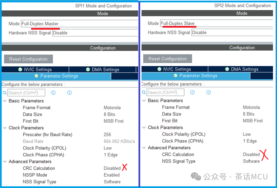
Here, we test and verify using the SPI1 and SPI2 of the STM32G4 chip. SPI1 is responsible for sending data based on interrupts, while SPI2 is responsible for receiving data based on DMA.
We first test the situation without enabling the CRC function.
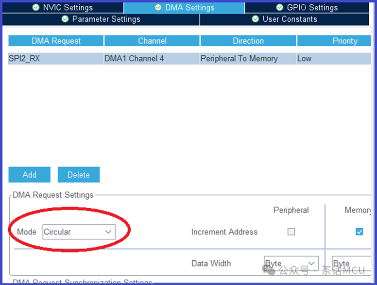
DMA reception for SPI2 is configured in circular mode.
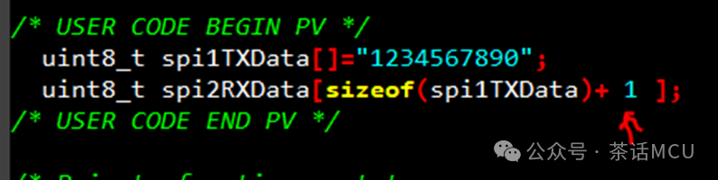
I defined two buffer arrays for sending and receiving:
/* USER CODE BEGIN PV */
uint8_t spi1TXData[]=”1234567890″;
uint8_t spi2RXData[sizeof(spi1TXData)];
/* USER CODE END PV */
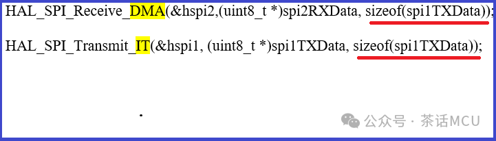
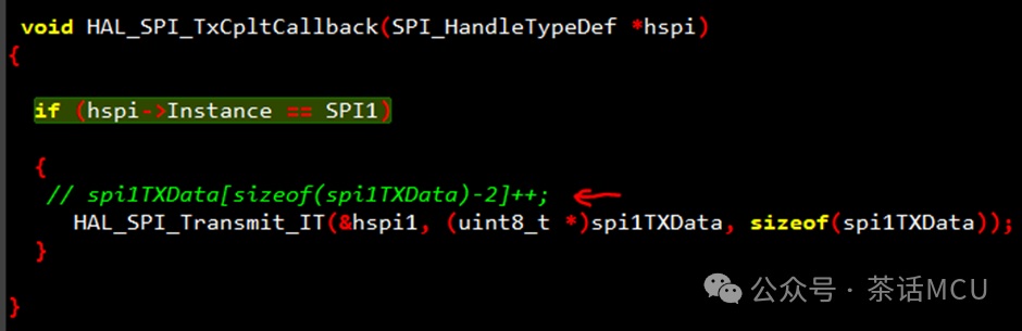
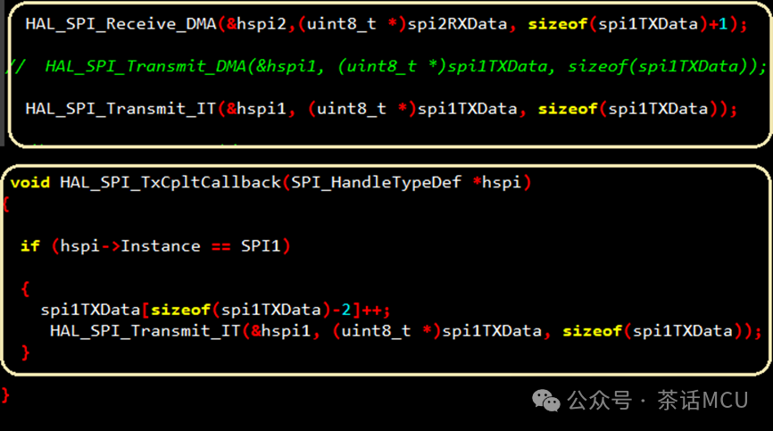
Two API functions related to SPI transmission and reception from the STM32HAL library, where SPI2 receives based on DMA and SPI1 sends based on interrupts.
In the SPI1 send complete interrupt, I restart the sending and change the 10th character each time to observe the effect. Below are the test results based on the previous configuration and code.
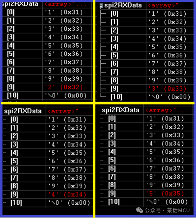
Clearly, according to the above configuration and code, the DMA received data is very stable, everything is normal.
What happens if we only enable the CRC function based on the above code and configuration? That is, we only add the CRC verification function of the SPI hardware based on the previous configuration. See the related configuration in the figure below:
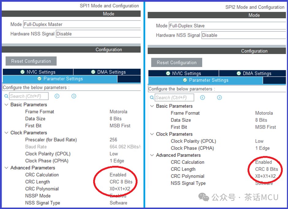
Here, we choose the 8-bit CRC mode, and everything else remains the same for testing.
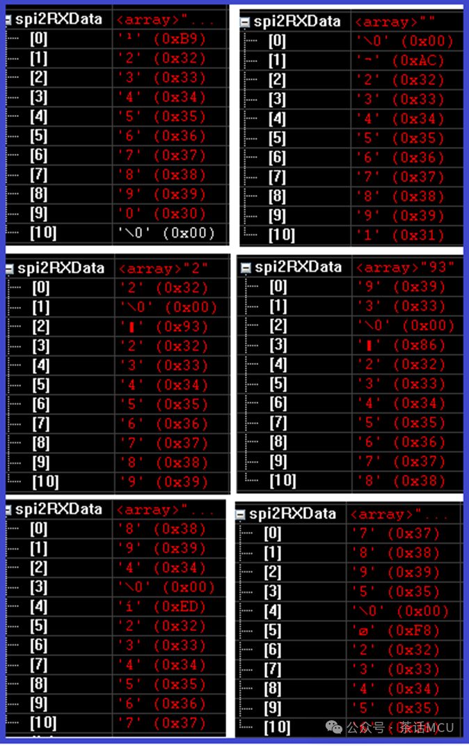
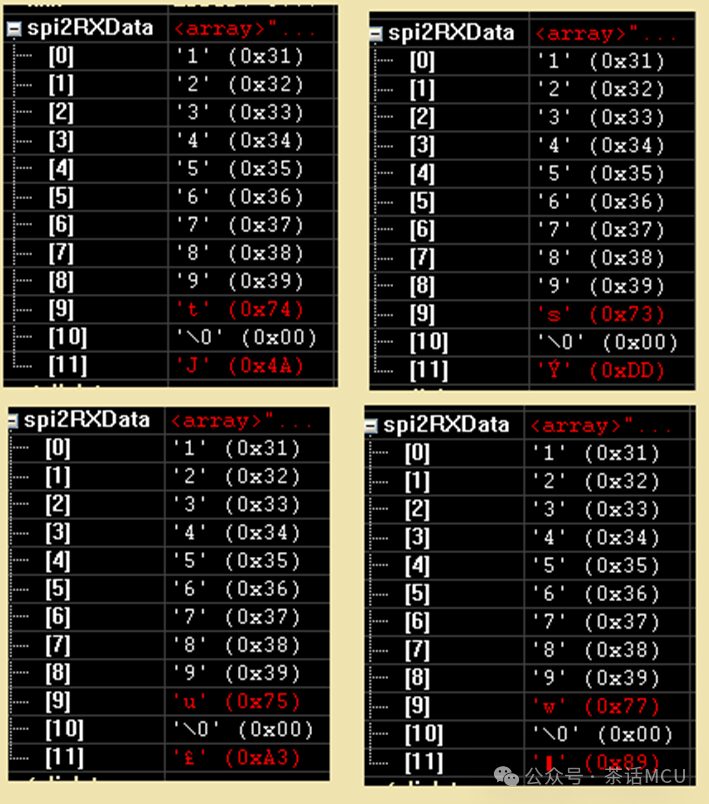
From the test results, it is clear that each time the received data is different, overall it feels like the data is rolling in memory, which is not what we expect. The only difference from before is that we enabled the SPI CRC function; why is this happening?
Based on the previous test code with slight adjustments, I fixed the data sent each time and observed the received data. In the figure below, the code that modifies the 10th character has been temporarily disabled.
After repeated tests, it was found that the received data keeps rolling, and the content generally does not change, but seems to have an extra piece of data that is not in the sending buffer, and this data remains unchanged. Specifically, there is an additional 0xb9 in the data.
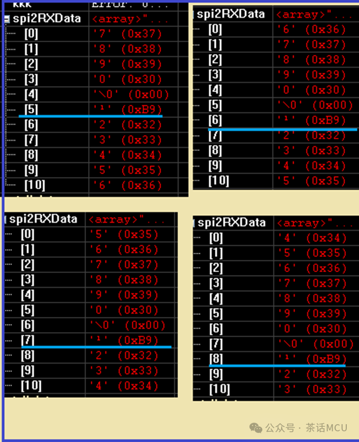
Could it be that this additional piece of data causes the DMA reception buffer to be one position short, and combined with the circular mode, leads to the rolling of the received data in memory?
Actually, we can find in the reference manual of the STM32 chip that when the SPI CRC function is enabled, for every frame of data sent, the hardware sends an additional CRC data for the receiver to verify. The earlier mentioned 0xb9 is the checksum sent from the sender.
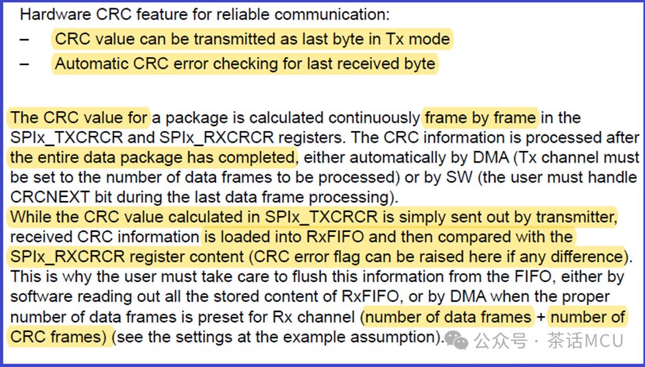
Sending data: The hardware automatically appends the CRC checksum at the end of the data frame, and the checksum is placed in the SPIx_TXCRCR register. During sending, only the actual data length needs to be configured.
Receiving data: The hardware automatically checks whether the last byte received is the correct CRC checksum, which requires ensuring that the reception buffer has enough space to receive both data and the CRC checksum.
The CRC checksum is stored in the SPIx_RXCRCR register, and the CRC checksum received from the sender is compared with the value in this register to determine if a checksum error has occurred.
Therefore, when enabling the CRC function, the receiving end should set the reception length to be the original data length plus the length needed for the CRC checksum; otherwise, if the length of the DMA reception buffer is less than the space required to store the checksum, a rolling phenomenon will occur in circular mode. If 8-bit CRC verification is selected, the reception length should be increased by an additional byte; if 16-bit CRC verification is selected, the reception length should be increased by two corresponding bytes.
Since this is the case, we will increase the reception length of SPI2 DMA configuration by an additional byte, keeping everything else unchanged to validate.
Upon re-validation, the data is correct, even in circular mode, the data content and its position in memory are very stable. The last byte is exactly the received checksum, and the last three data points are changing due to the modifications I made in the code, while the other data values and positions remain fixed. Refer to the test result screenshot below:
At this point, someone may ask, why does it work with the CRC function enabled when the DMA is configured in Normal mode, and the data length settings for both sending and receiving ends are the same?
This is because although the CRC code from the sending end is sent, the receiving end’s DMA length limitation does not allow it to receive the checksum, and the DMA only receives the basic data before stopping. Of course, the receiving end cannot perform checksum verification at this time because the checksum from the sending end has not been received. Moreover, because it is in Normal mode, the DMA must be reconfigured and restarted for each reception, which prevents the phenomenon of data misalignment in the reception buffer.
OK, today’s topic ends here, and we’ll talk again next time.