In PLC design, it is necessary to reserve spare I/O points to cope with the mechanical lifespan limitations of relay output modules. When an output point fails, operation can be quickly restored by rerouting the wiring to a spare terminal and modifying the program address. It is generally recommended to reserve 10-15% of I/O capacity, with the specific ratio determined by the importance of the equipment and maintenance strategy.

1、

PLC technology was once a high-end skill in the field of industrial control, and talents who mastered this technology were scarce and highly valued. For example, a certain elevator company in Guangzhou once rewarded a technician who successfully developed an elevator PLC control system with real estate, as this core technology relied heavily on imports from Japan at that time. Today, PLC programming has become widespread, and technicians with basic programming skills are everywhere, making program modifications no longer difficult.
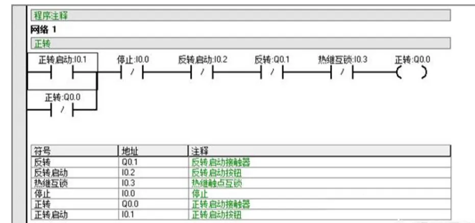
However, the key challenge in equipment maintenance lies in the deep understanding of specific production processes and equipment characteristics, which requires time accumulation and trial-and-error costs. Therefore, when purchasing equipment, companies must require manufacturers to provide PLC source code backups, which not only preserves technical documentation but also serves as an important measure to ensure production continuity, effectively avoiding production interruptions or maintenance difficulties caused by program issues.
2、

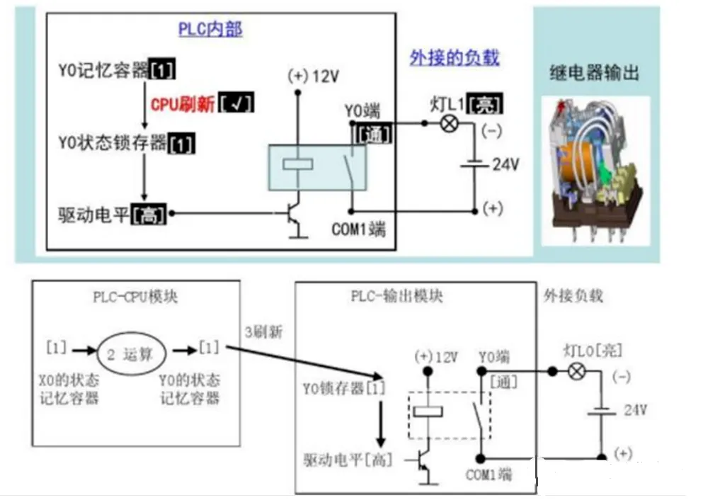
The most common failure in PLCs is the damage to the output circuit relay. These relays are typically designed to be compact, with coil voltages mostly in the range of 5-24V. Currently, there is a rich supply of alternative products available domestically, and when replacing, it is only necessary to ensure that the new relay’s coil voltage, contact capacity, and packaging size match the original model. After replacement, the equipment can usually return to normal operation quickly.
3、

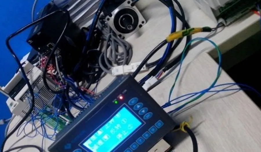
In industrial equipment maintenance, some experienced technicians often take a cautious approach to handling minor faults in key components, fearing that disassembly may lead to larger issues. In fact, as long as the operation is standardized and bold yet careful, the risks of electrical equipment repair can be controlled. Taking PLC maintenance as an example, the core considerations during disassembly are to protect the internal battery and connection wires—some PLCs use RAM to store data, and power loss can lead to program loss. Once this critical point is addressed, replacing relays and other operations only involve the power driver board, without touching the core area of the main board, thus the technical risk is relatively low.
4、

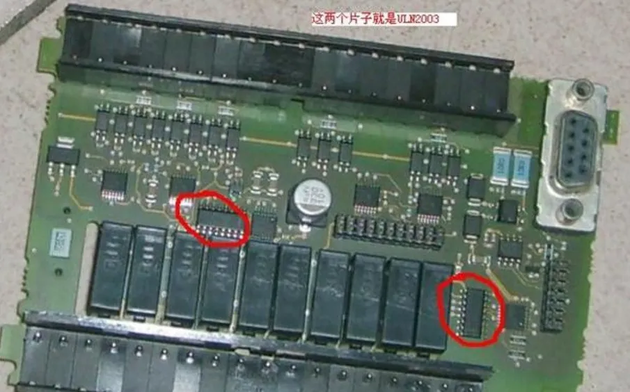
Replacing the PLC output relay can be accomplished with just a soldering iron and a desoldering pump. If the fault persists after replacement, further inspection of the driver circuit is necessary: it typically consists of transistors (such as 9013 and other low-power models, which can be interchanged), protection diodes, and current-limiting resistors. Replacing these components as a whole often resolves the issue. For circuits using driver ICs like ULN2003, simply replacing the integrated block can restore functionality.
5、

With a program backup in hand, simply use the corresponding PLC programming software and downloader to connect to the powered device to enable the online diagnostic function. This function can monitor the output I/O status in real-time, and technicians only need to switch the faulty output point to a spare channel and adjust the external wiring accordingly to quickly restore equipment operation. The entire process does not require complex debugging and is a common emergency response solution in industrial settings.
Previous Recommendations
Learn in one minute how to configure the Siemens most economical IO-IM60.
The wiring of PLC and the circuit control diagram of NPN and PNP proximity switches are quite informative!
Easily handle Modbus communication between PLCs and inverters!
Master this diagram to solve 80% of hardware faults in inverters.
The application and programming of the Modbus protocol in PLC communication, check this article for beginners!
How to use the FOR loop in SCL to make program design more efficient?
How to communicate between two Siemens S7-200 SMART PLCs? Detailed implementation steps →
How to achieve positioning functions of encoders using PLC control?
Have you encountered the “pits” of timer usage in S7-1200?
A case of using the BD board of Mitsubishi PLC to control two inverters in a polling manner.
How to read and write local real-time in S7-1200 PLC?
Collect and understand the basic knowledge essential for automation PLC!