

A complete PLC program is not just about getting the system to run; it also requires comprehensive comments, excellent architecture, good scalability, a complete alarm protection system, and a simulation system before operation. Today, I will share several PLC examples for reference!
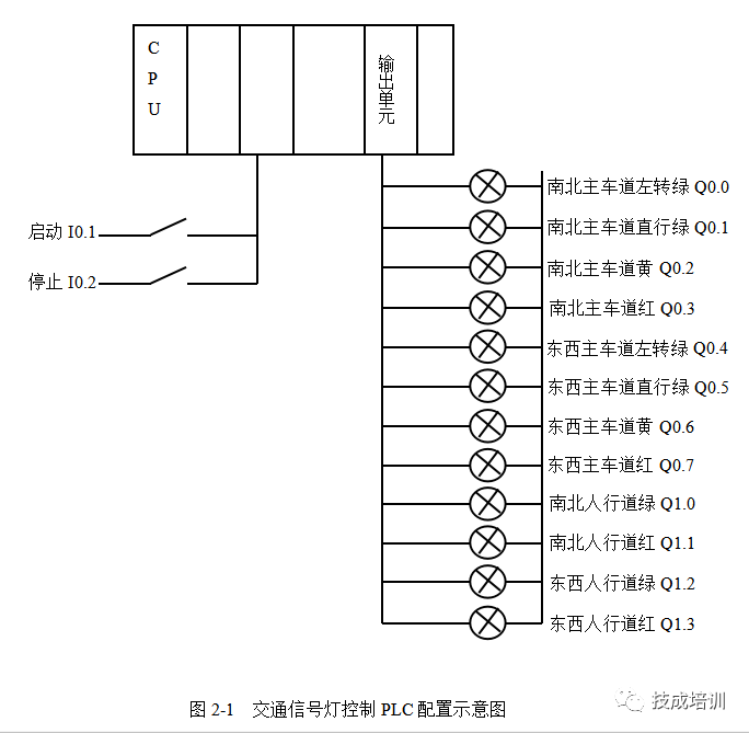
1. Traffic Light Control PLC Configuration Diagram
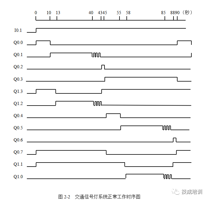
2. Traffic Light System Normal Working Sequence Diagram
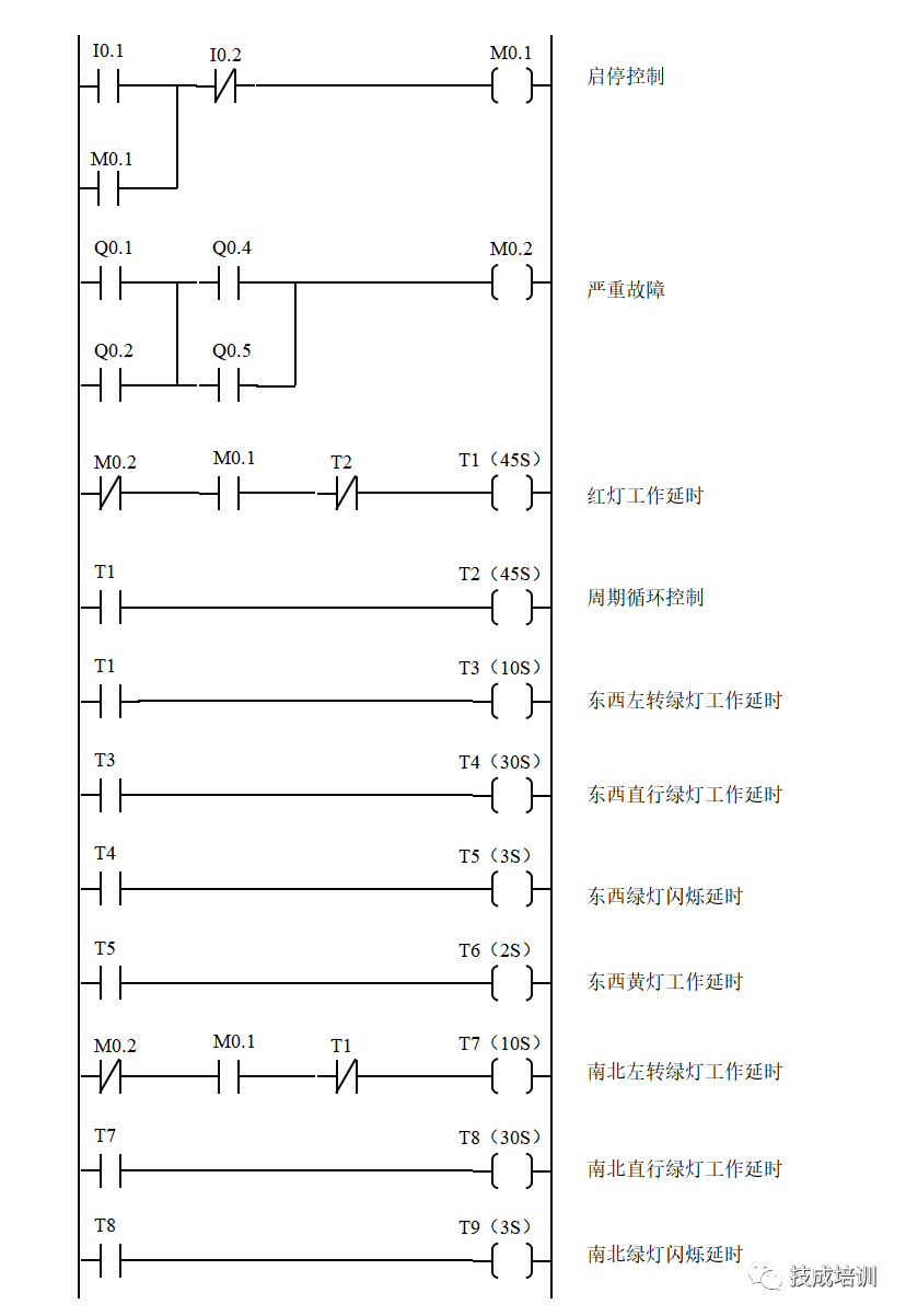
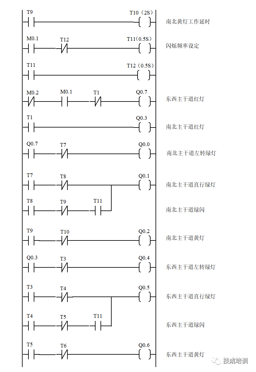
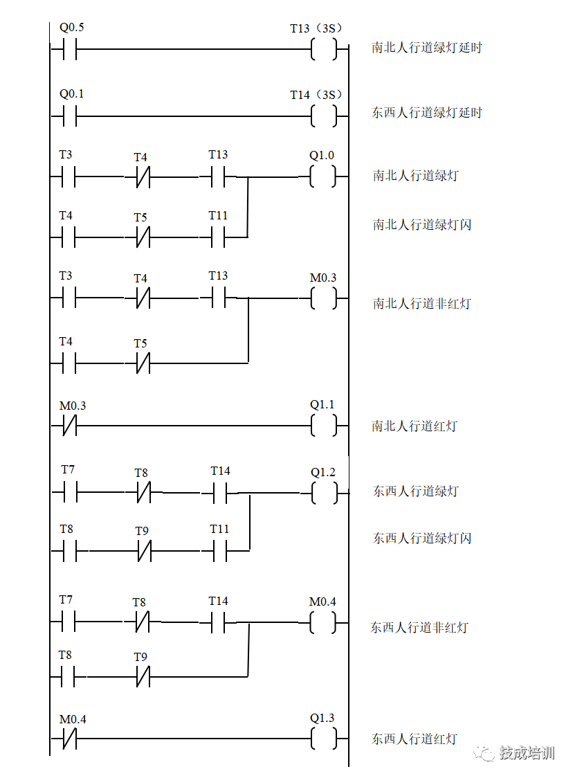
3. Ladder Diagram for Controlling Main Road Traffic Lights

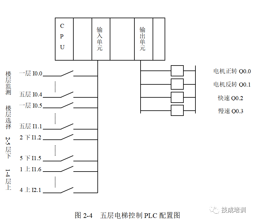
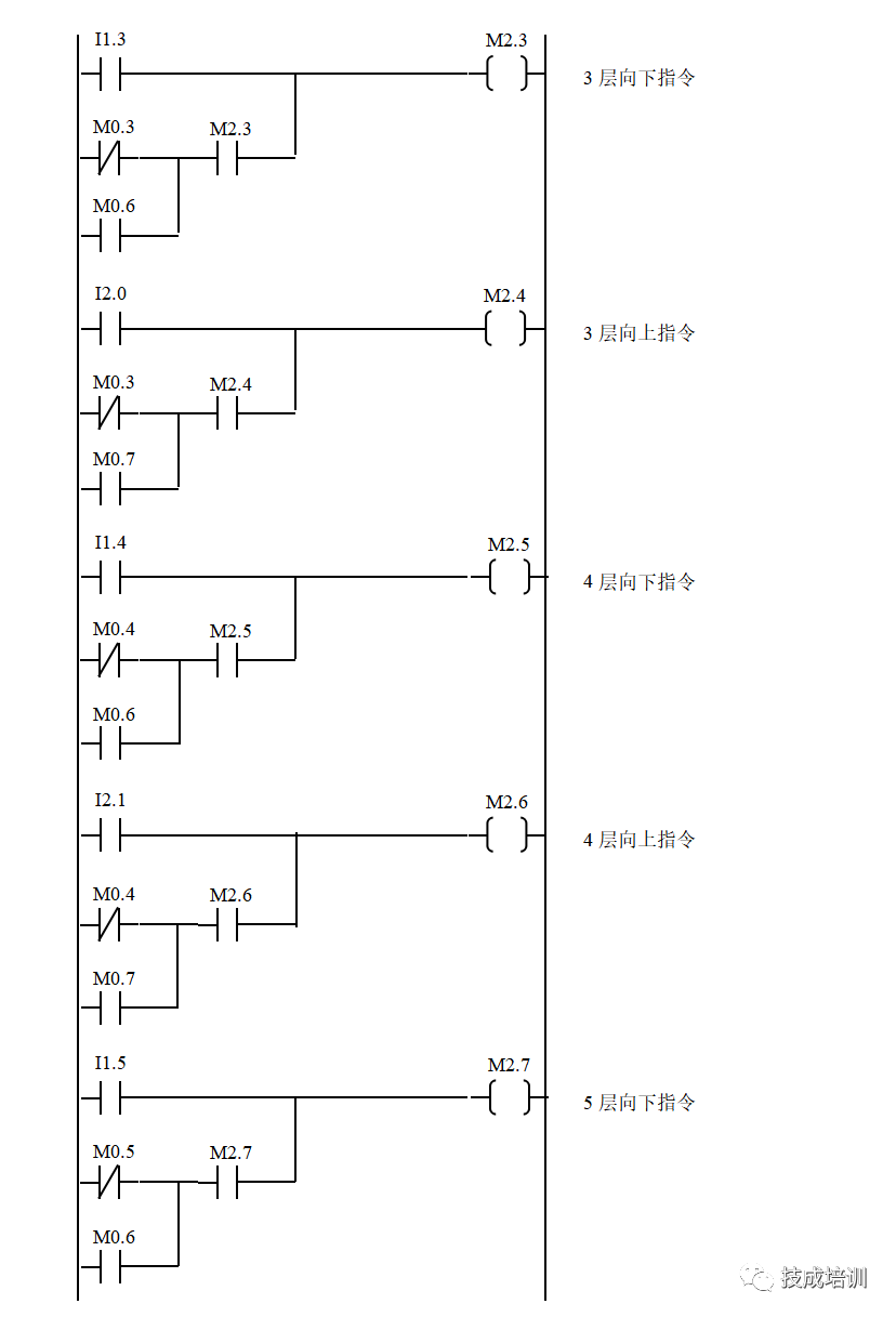
1. Five-Level Elevator Control PLC Configuration Diagram
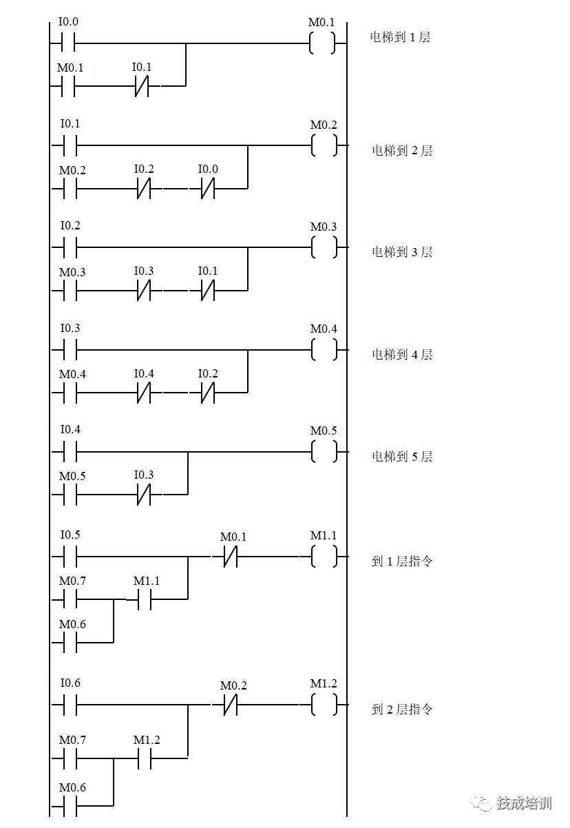
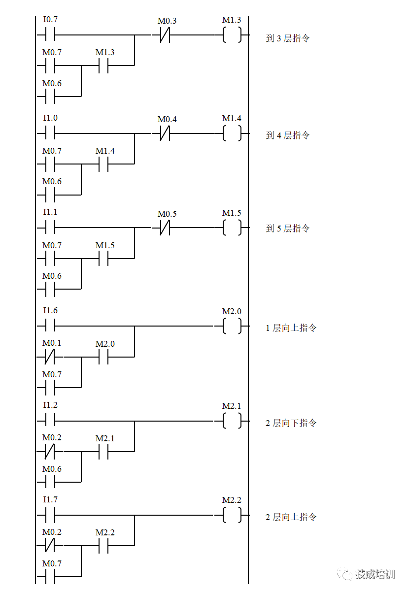
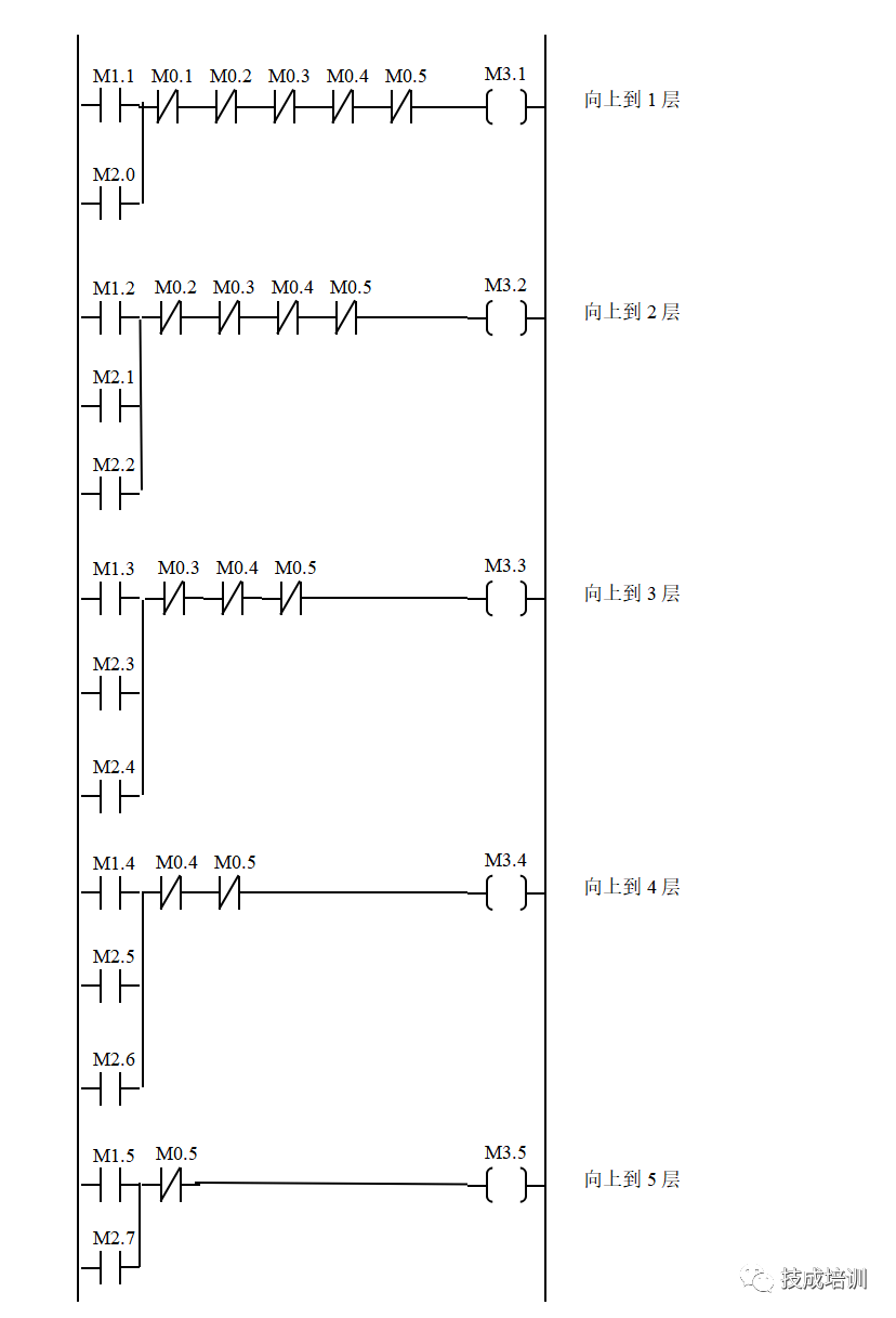
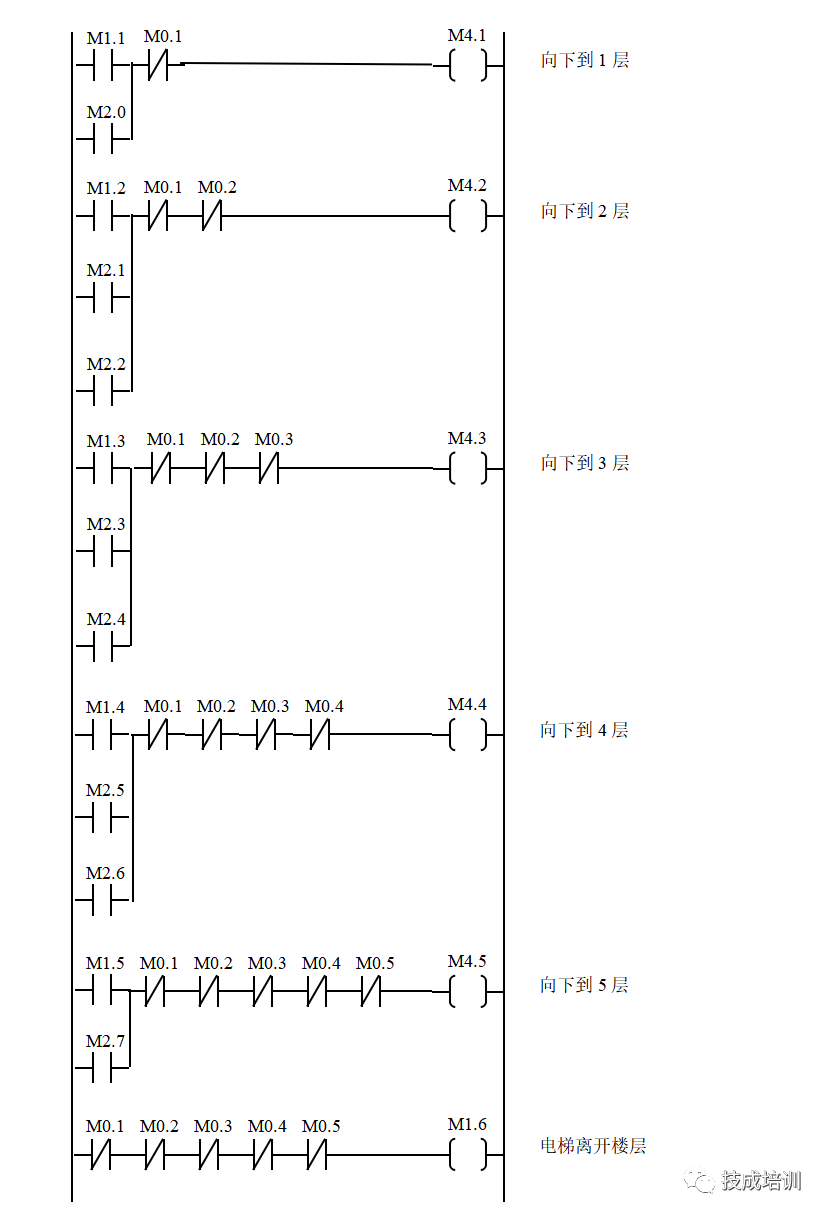
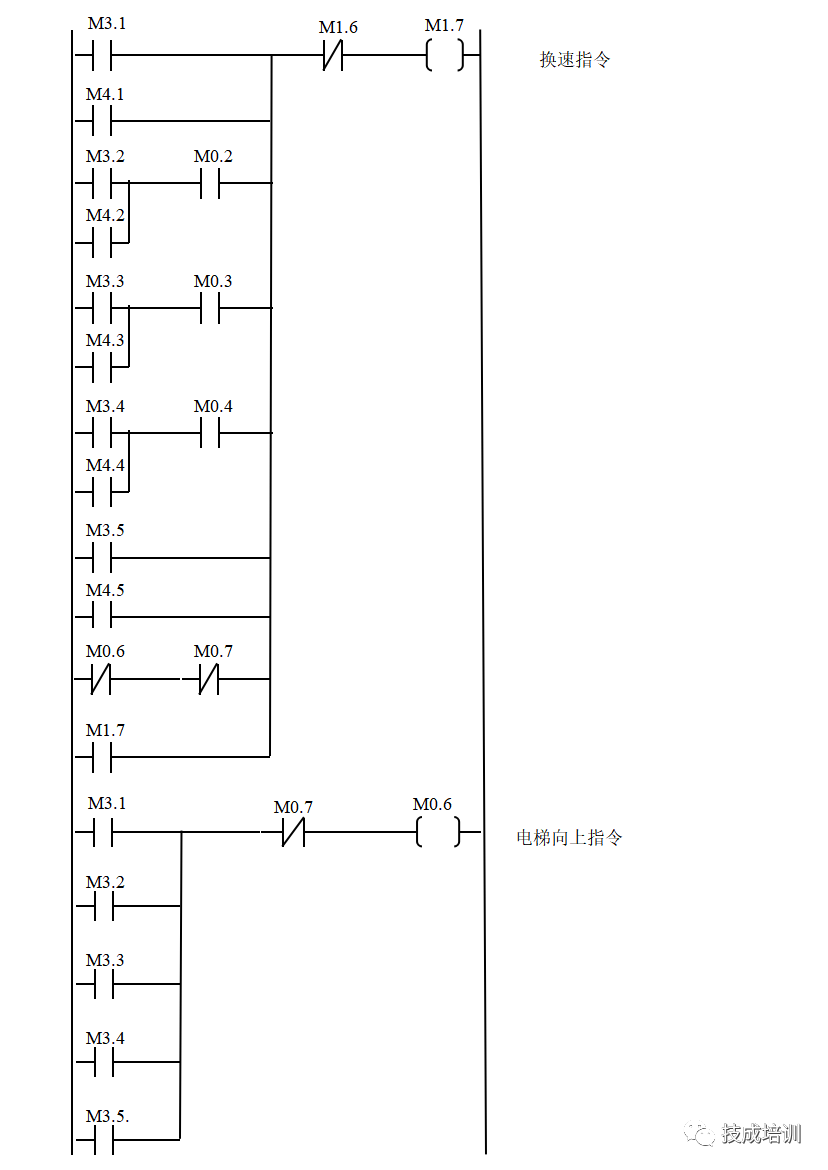
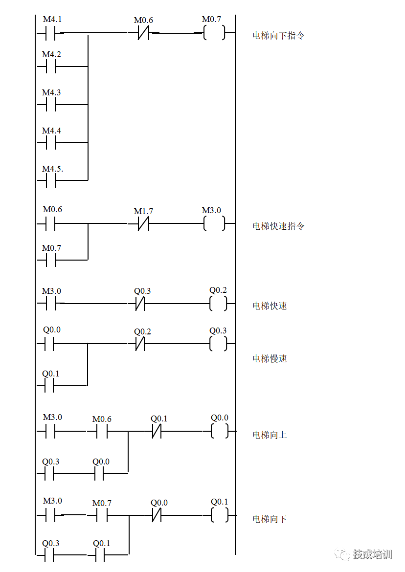
2. Ladder Diagram for Controlling Direction and Speed of the Five-Level Elevator

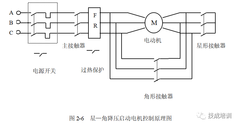
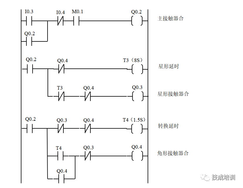
1. Star-Delta Soft Start Motor Control Principle Diagram
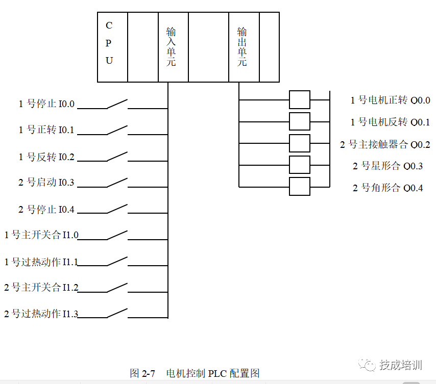
2. Motor Control PLC Configuration Diagram
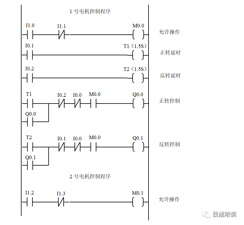
3. Ladder Diagram for Motor Control

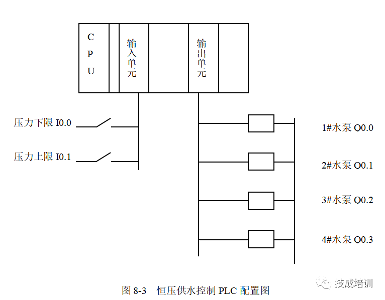
1. Constant Pressure Water Supply Control PLC Configuration Diagram
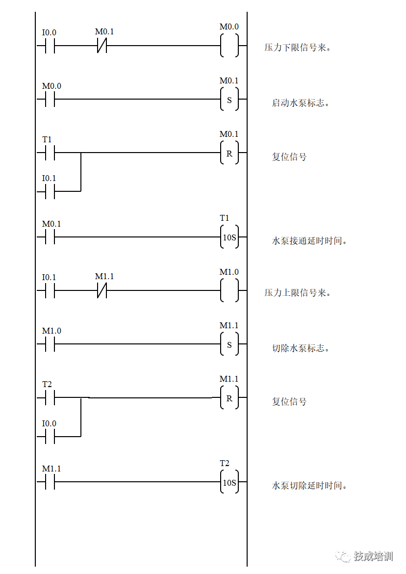
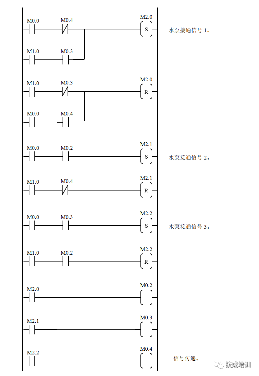
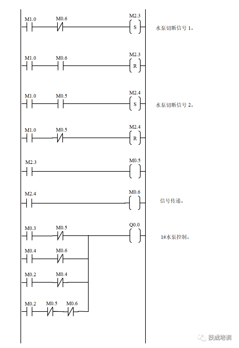
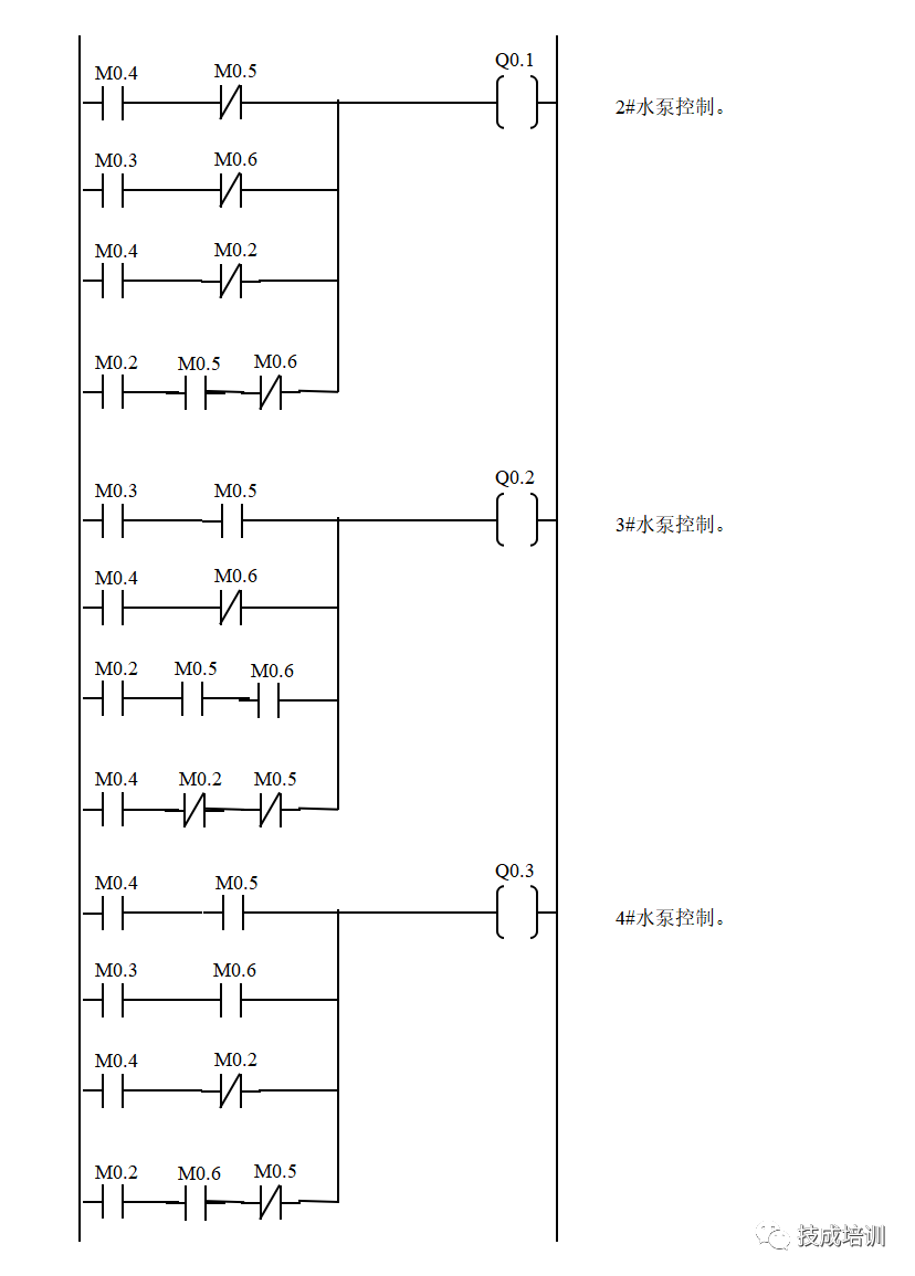
2. Constant Pressure Water Supply System Control Ladder Diagram

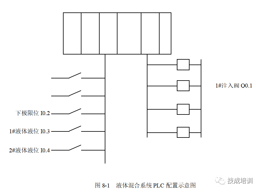
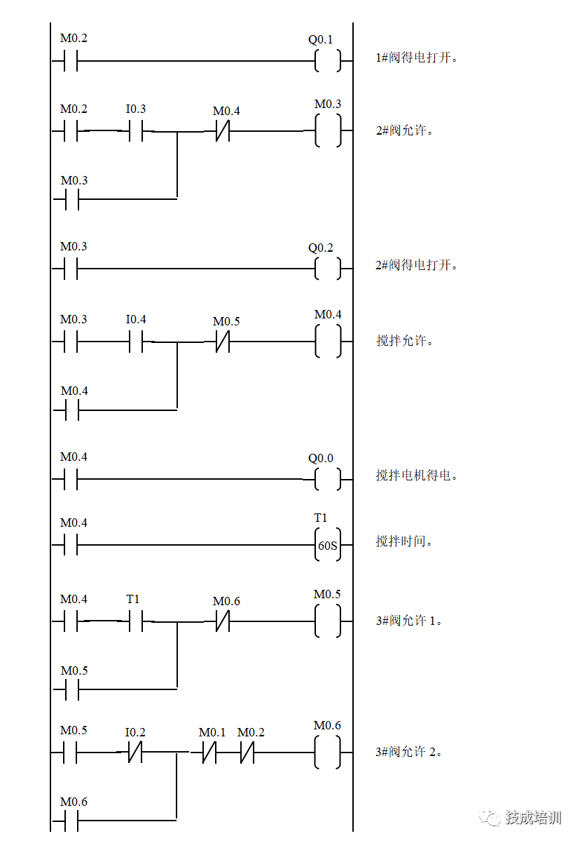
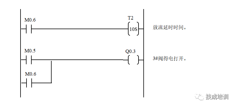
1. Liquid Mixing System PLC Configuration Diagram
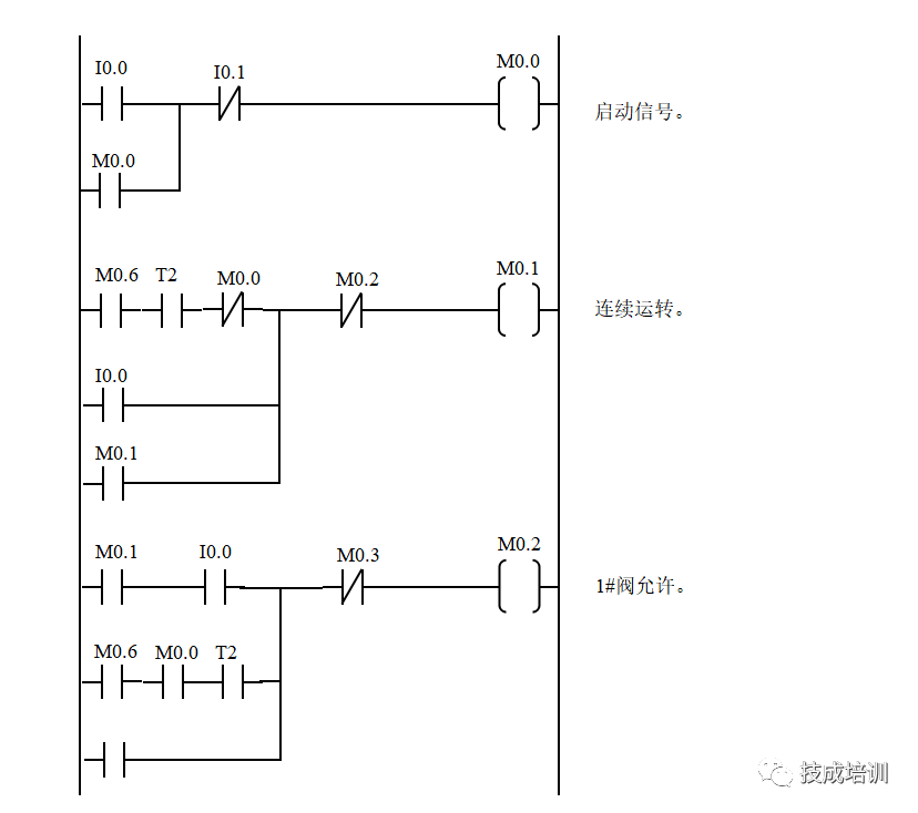
2. Liquid Mixing System Control Ladder Diagram

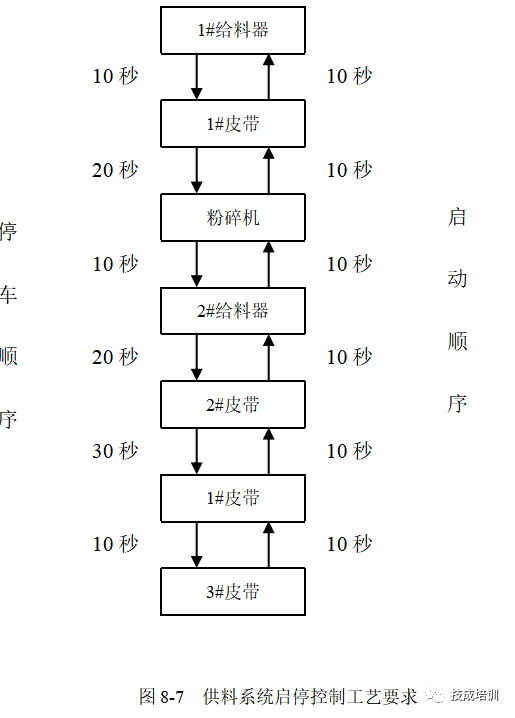
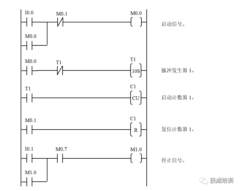
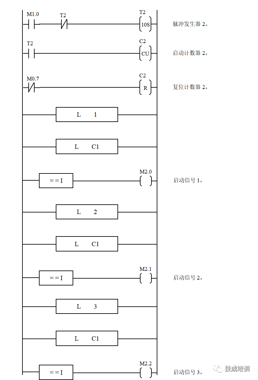
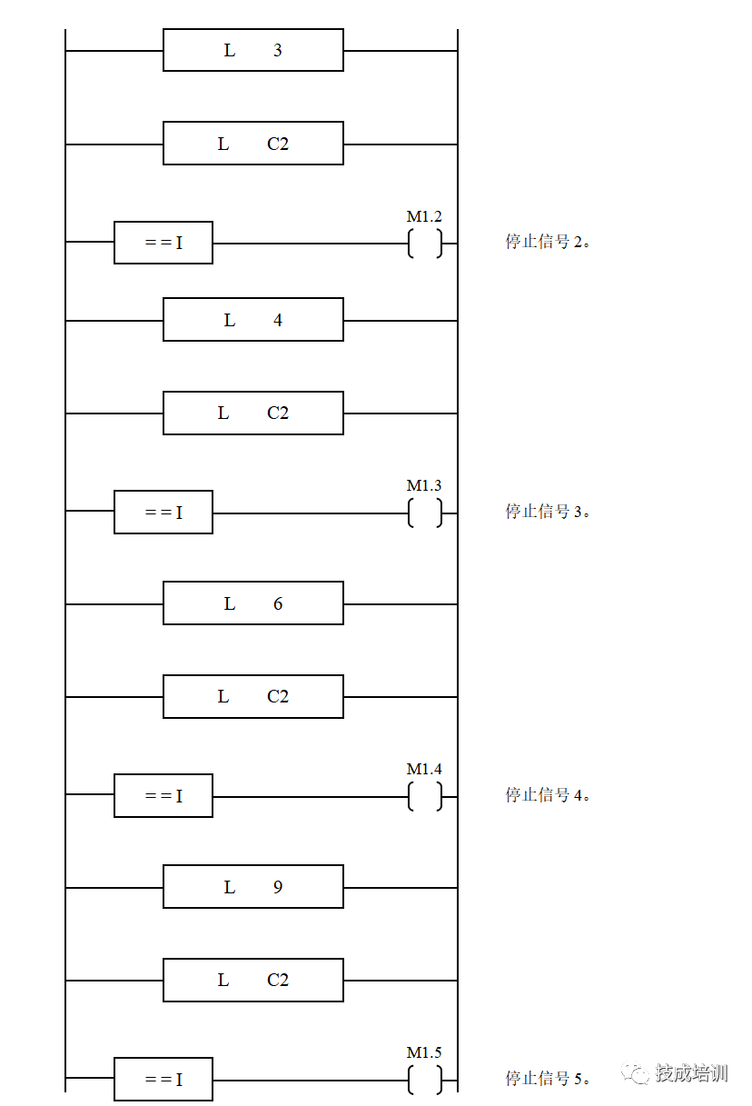
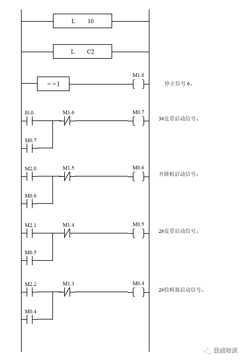
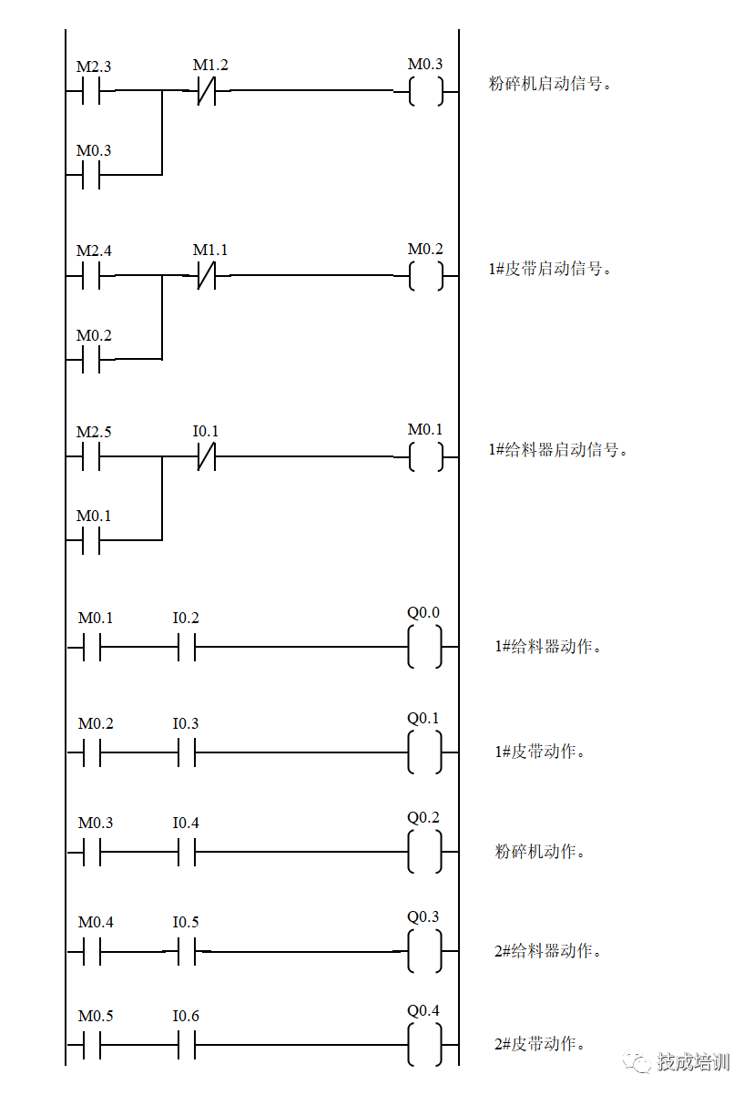
1. Feed System Start-Stop Control Process Requirements
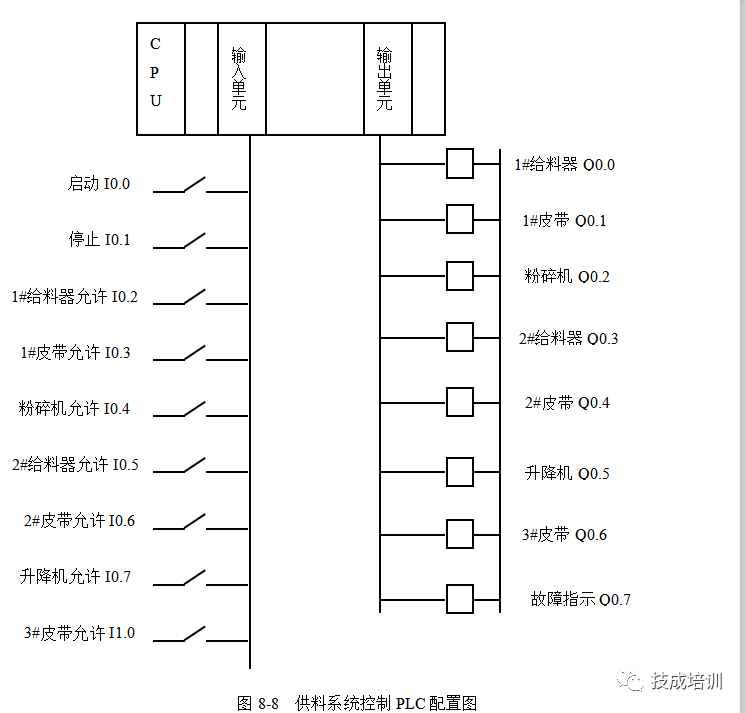
2. Feed System Control PLC Configuration Diagram
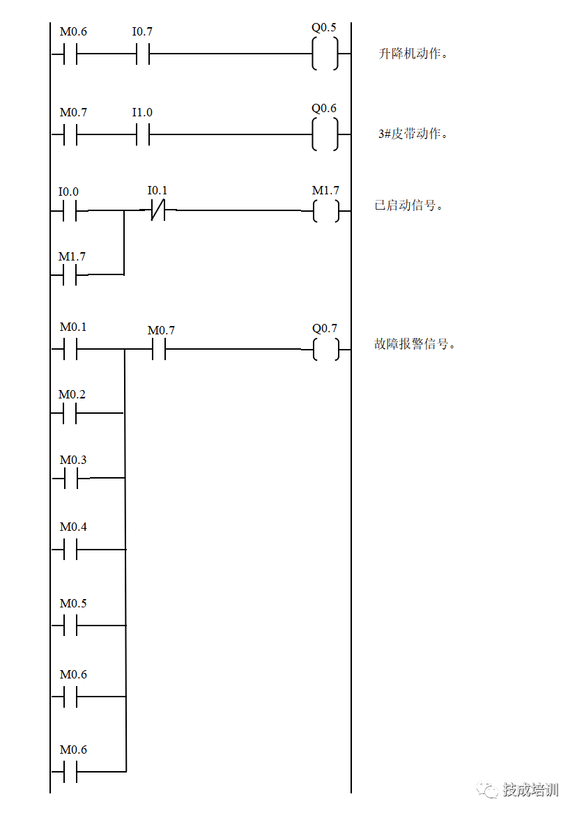
3. Feed System Control Ladder Diagram


1) When the PLC and the upper computer (or touchscreen) form a monitoring system, the screen often needs control modes like “Manual” and “Automatic” (generally, only one can be selected at a time). In the program, you can use the “MOV” instruction. For example: when “Manual” is selected, move constant 1 to register VB10, and when “Automatic” is selected, move 2 to the same register VB10. By checking the data in the register, you can determine the control mode of the system. This approach is easy to understand and avoids the complexity of interlocking programs.
2) When controlling analog quantities in the program, if the read analog value has little error, you can use time filtering to delay for a period. If the read data has a large error, other filtering methods, such as averaging, should be used. Relevant materials can be consulted.
3) During program debugging (especially when modifying equipment, and your program is added to the original equipment program), if a condition is met in the program statement but the output coil is not activated, check whether your program is between such statements, such as JUMP, go to, etc. Another possibility is that after an interrupt program, the condition is met but there is no output activation; usually, this program is not being scanned.
4) In sequential control programs, where one action is completed before moving to the next, I find the +10 +10 control mode very convenient. The idea is to preset a register, initialized to 0, and when the system starts, add 10 to it. At this point, the register equals 10, allowing the first action to be performed. After completing the first action, add another 10 to the register, making it 20 for the second action, and so on. By checking the data in the register, you can determine which action to complete. When a jump action is needed, you can add +20 +30, etc., depending on the actual need.
Why add 10 instead of 1? Because by adding 10, if a segment is inserted, you can choose any position among the 10 empty slots.
5) When designing the program, if a process fault occurs (not controlled by the control system), it is best to maintain the fault phenomenon and have light and sound alarms until the operator resets it, to make them aware of the fault. Otherwise, if the system stops, others may think the issue is with your program. Generally, this should be considered when designing a new system.
6) For frequently called subroutines, they can be made into submodules for frequent calls.
7) Since the movements of production machinery during the work cycle require a certain amount of time, and these times have limits, you can use these times as a reference. When the action to be detected starts, start a timer with a set time longer than the normal duration of that action by 20% to 30%. The timer’s output signal can be used for alarms or automatic shutdown devices. If the time for a certain action exceeds the specified time and does not transition to the next action, the timer will emit a fault signal, stopping the normal working cycle and starting the alarm or shutdown program, which is what we call over-cycle protection.
8) Some safety detection switches (like emergency stop buttons, safety light curtains, limit switches, etc.) should use normally closed (NC) inputs.
9) For safety and energy-saving considerations, try to design outputs to act only when needed, stopping output once the position is reached, instead of designing them to continuously output and only disconnect when stopping is required.
10) The principle of action for executing components should be not to move unnecessarily!
11) For single equipment control: a single device must have soft manual/automatic switching and a soft manual start/stop function. When switching from automatic to soft manual, the device must not stop; when switching from soft manual to automatic, the device’s start/stop depends on the automatic program.
12) Single devices (pumps, fans, and other large equipment) must rotate after running for 24 hours, and there must be a cumulative running time, except when the start/stop sequence is set by the upper computer, which is set by the operator.
Complete Question Bank for the 2023 Electrical Engineering Beginner Exam (Includes Answers)
Frequency Converter Fault Diagnosis Difficult? Just One Click!
Have you not owned this magical tool that can brush through all electrical exam questions with one click?
Which of the five major electrical drawing software (CAD, Eplan, CADe_simu…) would you pick?
Latest Electrical CAD Drawing Software, with Detailed Installation Tutorial!
Latest Electrical Drawing Software EPLAN, with Detailed Installation Tutorial!
Common Issues for Beginners Using S7-200 SMART Programming Software (Includes Download Links)
Super Comprehensive Electrical Calculation EXCEL Sheets, Automatically Generated! No Need for Electrical Calculations!
Bluetooth Headphones, Electrical/PLC Introductory Books Are Yours to Claim? Come Get Your Electrical Gifts!
Basic Skills for PLC Programming: Ladder Diagrams and Control Circuits (Includes 1164 Practical Mitsubishi PLC Cases)
Still Can’t Understand Electrical Diagrams? Grab the Basics of Electrical Diagram Recognition and Simulation Software, Quickly Get Started with Theory and Practice!
12 Free Electrical Engineering Video Courses, 10GB Software/E-Book Resources, 30 Days of Free Live Electrical Courses!
