PLC Control System Design: From Requirements to Implementation
The key to success in industrial automation projects lies in the rationality of system design and the reliability of program implementation. An excellent PLC control system must not only meet current production needs but also consider future scalability and maintainability. This article will detail the design methods of PLC control systems through a practical production line transformation project.
Requirements Analysis and System Planning
Requirements analysis is the cornerstone of the entire project. First, the following key elements need to be clarified:
Functional Requirements Analysis
-
Process flow sorting
1 Production Process:
2- Raw Material Conveying
3- Processing Control
4- Finished Product Output
5- Quality Inspection
6- Data Collection
-
Control requirements determination:
-
Automatic/manual mode switching
-
Device interlock protection
-
Exception handling mechanism
-
Production parameter adjustment
-
Data recording and traceability
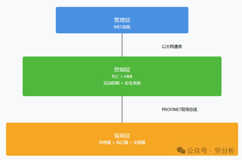
System Architecture Design
Hardware Configuration Plan
-
PLC selection
1 Hardware List:
2 CPU: S7-1516F-3 PN/DP
3 Power Supply: PM 190W 120/230VAC
4 DI: 32 points 24VDC
5 DO: 32 points 24VDC/0.5A
6 AI: 8 points 4-20mA
7 AO: 4 points 4-20mA
-
Network planning
-
Control Network: PROFINET
-
Management Network: Industrial Ethernet
-
Safety Network: PROFIsafe
Software Architecture Design
-
Program modular structure
 1// Program structure example
 2 ORGANIZATION_BLOCK "Main"
 3 BEGIN
 4    // System initialization
 5    CALL "Init_System"
 6
 7    // Device control
 8    CALL "Device_Control"
 9
10    // Data processing
11    CALL "Data_Process"
12
13    // Communication handling
14    CALL "Comm_Handle"
15
16    // Alarm handling
17    CALL "Alarm_Handle"
18 END_ORGANIZATION_BLOCK
Key Points of Program Implementation
Core Function Implementation
-
Device control module
 1 FUNCTION_BLOCK "DeviceControl"
 2 VAR_INPUT
 3    AutoMode : Bool;    // Automatic mode
 4    ManualMode : Bool;  // Manual mode
 5    StartCmd : Bool;    // Start command
 6    StopCmd : Bool;     // Stop command
 7 END_VAR
 8
 9 VAR
10    RunStatus : Bool;   // Running status
11    ErrorStatus : Bool; // Error status
12    Step : Int;        // Step number
13 END_VAR
-
Safety control implementation:
-
Emergency stop handling
-
Safety door monitoring
-
Light curtain protection
-
Over-limit protection
Data Processing and Communication
-
Data collection and storage
1 // Data recording structure
2 TYPE "ProductData"
3    STRUCT
4        BatchID : String[20];    // Batch number
5        TimeStamp : DTL;         // Timestamp
6        Parameters : Array[1..10] of Real;  // Process parameters
7        Quality : Int;           // Quality level
8    END_STRUCT;
9 END_TYPE
-
MES communication interface
-
Production instruction reception
-
Real-time data upload
-
Alarm information push
-
Recipe management
Debugging and Verification Process
-
Module testing
-
Unit function verification
-
Interface data check
-
Boundary condition testing
-
Joint debugging testing
-
Device collaborative operation
-
Communication stability
-
Exception handling verification
-
Performance index testing
Practical suggestions:
-
Detailed requirement documentation
-
Standardized program comments
-
Complete testing records
-
Reliable backup plan
Extended applications:
-
Energy consumption management function
-
Device pre-diagnosis
-
Remote maintenance interface
-
Production optimization algorithms