1.
【Experiment Objective】
(1)Understand the communication principles between the host and the development board.;
(2)Understand the working principles of the vibration sensor and how to operate it.
2.【Experiment Environment】
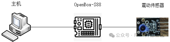
Figure1 Example of Experiment Environment
Required equipment for the experiment:
(1)One OpenBox-S88 device
(2)One PC host
(3)One network cable
(4)One vibration sensor
(5)Several Dupont wires
3.【Experiment Configuration】
Operating System: Windows.
Software Configuration: Mobaxterm.
Network Configuration:The network configuration information for host X is as follows:
|
IP |
192.168.1.28 |
|
Netmask |
255.255.255.0 |
|
Gateway |
192.168.1.1 |
Connect the vibration sensor encoder data (DT) pin to the pin in the blue box in the figure below. It is necessary to record the pin number for effective output during subsequent command execution (pin numbering starts from 0 from left to right).
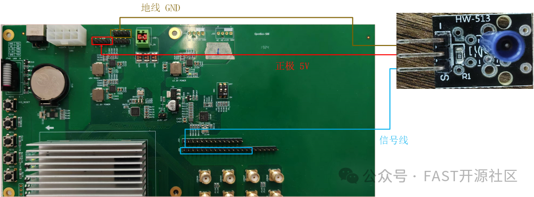 Figure2 Wiring Diagram of the Board
Interface Pins:
| Pin Silk Screen | Description |
| + | Power positive, connect to5V |
| – | Power negative, connect to ground |
| S | Signal pin, connect toFPGA development board |
4.【Experiment Content】
Connect the vibration sensor to the FPGA pins, trigger the vibration sensor, and observe the corresponding signal trigger and the encapsulated message sent.
| Principle:The inertial electric sensor consists of a fixed part, a movable part, and a supporting spring part. To make the sensor work in the displacement sensor state, the mass of the movable part should be sufficiently large, while the stiffness of the supporting spring should be sufficiently small, allowing the sensor to have a sufficiently low natural frequency. From the perspective of mechanical reception principles, the inertial electric sensor is a displacement sensor. Since the principle of electromechanical conversion applies Faraday’s law of electromagnetic induction, the electromotive force generated is proportional to the measured vibration velocity, so it is actually a velocity sensor. |
5.【Experiment Steps】
(1)The experiment mainly transmits data through the hardware FPGA, and the FPGA needs to be set to the corresponding logic. First, enter the system, and after entering, switch the system user to the root account, with the password 123123.

Figure 3 Step Diagram-1
(2)Open Vivado, select to open hardware, and connect the FPGA development board to the host.
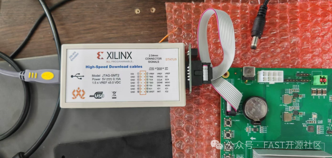
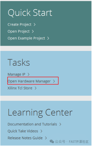
Select to automatically connect to the board
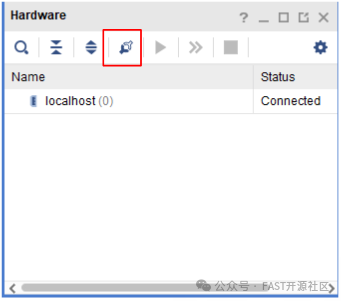
After the connection is complete, burn the corresponding code and enter the logic analyzer of the corresponding code.
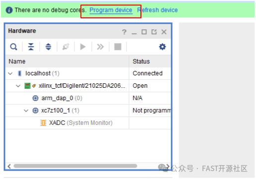
(3)Set the FPGA to input mode, connect the corresponding light sensor to the corresponding GPIO pin, and after configuration, the pin will be at a high level.
|
mem_rw 45000000 10000 0 00000001 mem_rw 45000000 10000 4 90000000 mem_rw 45000000 10000 8 30000000 mem_rw 45000000 10000 4 91000000 mem_rw 45000000 10000 8 00000000 mem_rw 45000000 10000 4 800ff000 mem_rw 45000000 10000 8 00000000 |

Figure 4 Result Diagram-1
(4)Input control commands, lightly tap the vibration sensor, and observe that the corresponding GPIO pin is pulled low through signal capture in Vivado.
|
mem_rw 45000000 10000 4 90000000 mem_rw 45000000 10000 8 10000008 mem_rw 45000000 10000 4 91000000 mem_rw 45000000 10000 8 0001E848 mem_rw 45000000 10000 4 800ff000 mem_rw 45000000 10000 8 00000000 mem_rw 45000000 10000 4 90000000 mem_rw 45000000 10000 8 1000000c mem_rw 45000000 10000 4 91000000 mem_rw 45000000 10000 8 0000186a mem_rw 45000000 10000 4 800ff000 mem_rw 45000000 10000 8 00000000 mem_rw 45000000 10000 4 90000000 mem_rw 45000000 10000 8 10000004 mem_rw 45000000 10000 4 91000000 mem_rw 45000000 10000 8 00000001 mem_rw 45000000 10000 4 800ff000 mem_rw 45000000 10000 8 00000000 mem_rw 45000000 10000 4 80001010 mem_rw 45000000 10000 8 00000000 mem_rw 45000000 10000 4 80004010 mem_rw 45000000 10000 8 00000000 mem_rw 45000000 10000 4 80010010 mem_rw 45000000 10000 8 00000000 mem_rw 45000000 10000 4 80011010 mem_rw 45000000 10000 8 00000000 mem_rw 45000000 10000 4 b0000000 mem_rw 45000000 10000 8 80001010 mem_rw 45000000 10000 4 b0001000 mem_rw 45000000 10000 8 80004010 mem_rw 45000000 10000 4 b0002000 mem_rw 45000000 10000 8 80010010 mem_rw 45000000 10000 4 b0003000 mem_rw 45000000 10000 8 80011010 mem_rw 45000000 10000 4 90000000 mem_rw 45000000 10000 8 20000001 mem_rw 45000000 10000 4 91000000 mem_rw 45000000 10000 8 00000003 mem_rw 45000000 10000 4 800ff000 mem_rw 45000000 10000 8 00000000 mem_rw 45000000 10000 4 90000000 mem_rw 45000000 10000 8 20000000 mem_rw 45000000 10000 4 91000000 mem_rw 45000000 10000 8 00000001 mem_rw 45000000 10000 4 800ff000 mem_rw 45000000 10000 8 00000000 |

Figure 5 Result Diagram-2
(5)Input the read command to read the value in the message counter. It can be observed that after the signal is triggered, the FPGA logic packages the signal into a message and sends it to the host computer.
| mem_rw 45000000 10000 80 |

Figure 6 Result Diagram-3
6.【Experiment Reflection】
(1)How many types of vibration sensors are there? In which different fields can they be applied?