1Module Source>>>
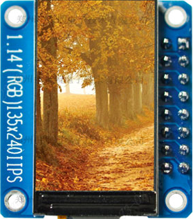
Module Physical Display:
Data Download Link:https://pan.baidu.com/s/1cVzawBFj3ZkGml5Dj-368A
Data Extraction Code:8888
2Specifications>>>
The following information is from the manufacturer’s documentation
Operating Voltage:3.3V
Operating Current:20MA
Module Size:31.4(H) x 28(V) MM
Pixel Size:135(H) x 240(V)RGB
Driver Chip:ST7789V
Communication Protocol:8-bit Parallel
Pin Count:16 Pin (2.54mm pitch header)
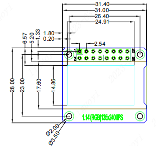
Size Parameters
-
Import the source code into the project;
-
Make rough modifications based on compilation errors;
-
Modify pin configurations;
-
Modify timing configurations;
-
Porting verification.
3.1View Documentation
Open the manufacturer’s example documentation (example download can be found in the cloud link). The specific path is shown in the image below.
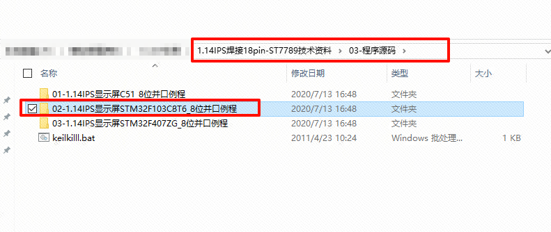
Example Path
Copy the 【LCD】 folder from the manufacturer’s documentation path to your own project. Your project must have at least a millisecond delay function. (The project can refer to the introductory manual project template)
Open your project and import the .c and .h files that we just copied.
Change sys.h in the lcd_init.h file to board.h, and also change sys.h in the lcd.h file to board.h.
(Expand the project directory of lcd.c and lcd_init.c on the left, and you will find lcd_init.h and lcd.h)
Comment out delay.h in the lcd_init.c file, and also comment out delay.h in the lcd.c file.
Define three macros, u32, u16, and u8, in both lcd_init.h and lcd.h files.
#ifndef u8#define u8 uint8_t#endif#ifndef u16#define u16 uint16_t#endif#ifndef u32#define u32 uint32_t#endif3.3Pin SelectionThis screen requires the setup of 8 interfaces, specific interface descriptions are shown in the table below.
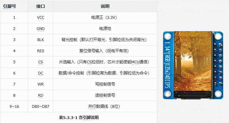
After selecting the pins, enter the project to start writing the screen pin initialization code.
For ease of future porting, I defined each pin in lcd_init.h as a macro, which can be modified as needed later.
//-----------------LCD Port Porting----------------// 1-VCC --3.3V// 2-GND --GND// 3-BLK --PA0// 4-RES --PA1// 5-CS --PA2// 6-DC --PA3// 7-WR --PA4// 8-RD --PA5// 9-DB0 --PA6//10-DB1 --PA7//11-DB2 --PB0//12-DB3 --PB1//13-DB4 --PB10//14-DB5 --PB11//15-DB6 --PB12//16-DB7 --PB13#define RCC_LCD1_ENABLE() __RCC_GPIOA_CLK_ENABLE()#define RCC_LCD2_ENABLE() __RCC_GPIOB_CLK_ENABLE()//RD#define PORT_LCD_RD CW_GPIOA#define GPIO_LCD_RD GPIO_PIN_5//WR#define PORT_LCD_WR CW_GPIOA#define GPIO_LCD_WR GPIO_PIN_4//CS#define PORT_LCD_CS CW_GPIOA#define GPIO_LCD_CS GPIO_PIN_2//DC#define PORT_LCD_DC CW_GPIOA#define GPIO_LCD_DC GPIO_PIN_3//RES#define PORT_LCD_RES CW_GPIOA#define GPIO_LCD_RES GPIO_PIN_1//BLK#define PORT_LCD_BLK CW_GPIOA#define GPIO_LCD_BLK GPIO_PIN_0//DB0#define PORT_LCD_DB0 CW_GPIOA#define GPIO_LCD_DB0 GPIO_PIN_6//DB1#define PORT_LCD_DB1 CW_GPIOA#define GPIO_LCD_DB1 GPIO_PIN_7//DB2#define PORT_LCD_DB2 CW_GPIOB#define GPIO_LCD_DB2 GPIO_PIN_0//DB3#define PORT_LCD_DB3 CW_GPIOB#define GPIO_LCD_DB3 GPIO_PIN_1//DB4#define PORT_LCD_DB4 CW_GPIOB#define GPIO_LCD_DB4 GPIO_PIN_10//DB5#define PORT_LCD_DB5 CW_GPIOB#define GPIO_LCD_DB5 GPIO_PIN_11//DB6#define PORT_LCD_DB6 CW_GPIOB#define GPIO_LCD_DB6 GPIO_PIN_12//DB7#define PORT_LCD_DB7 CW_GPIOB#define GPIO_LCD_DB7 GPIO_PIN_13Modify the void LCD_GPIO_Init(void) in the lcd_init.c source code to the following code.
void LCD_GPIO_Init(void){ GPIO_InitTypeDef GPIO_InitStruct; // GPIO initialization structure RCC_LCD1_ENABLE(); // Enable GPIO clock 1 RCC_LCD2_ENABLE(); // Enable GPIO clock 2 GPIO_InitStruct.Pins = GPIO_LCD_RD| // GPIO pins GPIO_LCD_WR| GPIO_LCD_CS| GPIO_LCD_DC| GPIO_LCD_RES| GPIO_LCD_BLK| GPIO_LCD_DB0| GPIO_LCD_DB1; GPIO_InitStruct.Mode = GPIO_MODE_OUTPUT_PP; // Push-pull output GPIO_InitStruct.Speed = GPIO_SPEED_HIGH; // High output speed GPIO_Init(PORT_LCD_RD, &GPIO_InitStruct); // Initialize GPIO_InitStruct.Pins = GPIO_LCD_DB2| GPIO_LCD_DB3| GPIO_LCD_DB4| GPIO_LCD_DB5| GPIO_LCD_DB6| GPIO_LCD_DB7; GPIO_Init(PORT_LCD_DB2, &GPIO_InitStruct); // Initialize}Change the LCD port definition macros in lcd_init.h to the style shown on the right.
//-----------------LCD Port Definition----------------#define LCD_RES_Set() GPIO_WritePin(PORT_LCD_RES, GPIO_LCD_RES, GPIO_Pin_SET)//RES#define LCD_CS_Set() GPIO_WritePin(PORT_LCD_CS, GPIO_LCD_CS, GPIO_Pin_SET)//CS#define LCD_DC_Set() GPIO_WritePin(PORT_LCD_DC, GPIO_LCD_DC, GPIO_Pin_SET)//DC#define LCD_WR_Set() GPIO_WritePin(PORT_LCD_WR, GPIO_LCD_WR, GPIO_Pin_SET)//WR#define LCD_RD_Set() GPIO_WritePin(PORT_LCD_RD, GPIO_LCD_RD, GPIO_Pin_SET)//RD#define LCD_BLK_Set() GPIO_WritePin(PORT_LCD_BLK, GPIO_LCD_BLK, GPIO_Pin_SET)//BLK#define LCD_RES_Clr() GPIO_WritePin(PORT_LCD_RES, GPIO_LCD_RES, GPIO_Pin_RESET)//RES#define LCD_CS_Clr() GPIO_WritePin(PORT_LCD_CS, GPIO_LCD_CS, GPIO_Pin_RESET)//CS#define LCD_DC_Clr() GPIO_WritePin(PORT_LCD_DC, GPIO_LCD_DC, GPIO_Pin_RESET)//DC#define LCD_WR_Clr() GPIO_WritePin(PORT_LCD_WR, GPIO_LCD_WR, GPIO_Pin_RESET)//WR#define LCD_RD_Clr() GPIO_WritePin(PORT_LCD_RD, GPIO_LCD_RD, GPIO_Pin_RESET)//RD#define LCD_BLK_Clr() GPIO_WritePin(PORT_LCD_BLK, GPIO_LCD_BLK, GPIO_Pin_RESET)//BLK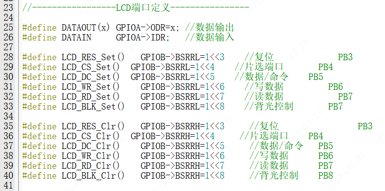 Source Port Definition
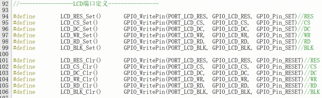 Modified Port Definition
Since this is a parallel screen, it transmits 8 bits of data, with one wire per bit, meaning 8 bits of data require 8 wires. Therefore, we need to load an 8-bit data onto 8 data lines. Add the following code in lcd_init.h for easier data transmission and port modification later.
// x ? set 1 : set 0#define BIT_DB7(x) { GPIO_WritePin( PORT_LCD_DB7, GPIO_LCD_DB7, x?GPIO_Pin_SET:GPIO_Pin_RESET); }#define BIT_DB6(x) { GPIO_WritePin( PORT_LCD_DB6, GPIO_LCD_DB6, x?GPIO_Pin_SET:GPIO_Pin_RESET); }#define BIT_DB5(x) { GPIO_WritePin( PORT_LCD_DB5, GPIO_LCD_DB5, x?GPIO_Pin_SET:GPIO_Pin_RESET); }#define BIT_DB4(x) { GPIO_WritePin( PORT_LCD_DB4, GPIO_LCD_DB4, x?GPIO_Pin_SET:GPIO_Pin_RESET); }#define BIT_DB3(x) { GPIO_WritePin( PORT_LCD_DB3, GPIO_LCD_DB3, x?GPIO_Pin_SET:GPIO_Pin_RESET); }#define BIT_DB2(x) { GPIO_WritePin( PORT_LCD_DB2, GPIO_LCD_DB2, x?GPIO_Pin_SET:GPIO_Pin_RESET); }#define BIT_DB1(x) { GPIO_WritePin( PORT_LCD_DB1, GPIO_LCD_DB1, x?GPIO_Pin_SET:GPIO_Pin_RESET); }#define BIT_DB0(x) { GPIO_WritePin( PORT_LCD_DB0, GPIO_LCD_DB0, x?GPIO_Pin_SET:GPIO_Pin_RESET); }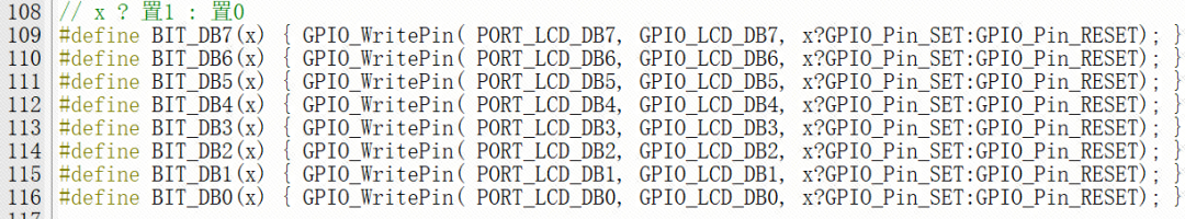
In the lcd_init.c file, find the void LCD_Writ_Bus(u8 dat) function and modify it as follows.
void LCD_Writ_Bus(u8 dat){ LCD_CS_Clr(); LCD_WR_Clr(); BIT_DB7( (dat>>7)&0x01 ); BIT_DB6( (dat>>6)&0x01 ); BIT_DB5( (dat>>5)&0x01 ); BIT_DB4( (dat>>4)&0x01 ); BIT_DB3( (dat>>3)&0x01 ); BIT_DB2( (dat>>2)&0x01 ); BIT_DB1( (dat>>1)&0x01 ); BIT_DB0( (dat>>0)&0x01 ); LCD_WR_Set(); LCD_CS_Set();}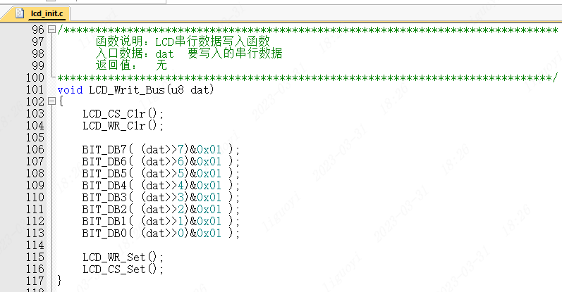
The porting is now complete.
4Porting Verification>>>
Enter the following code in main.c
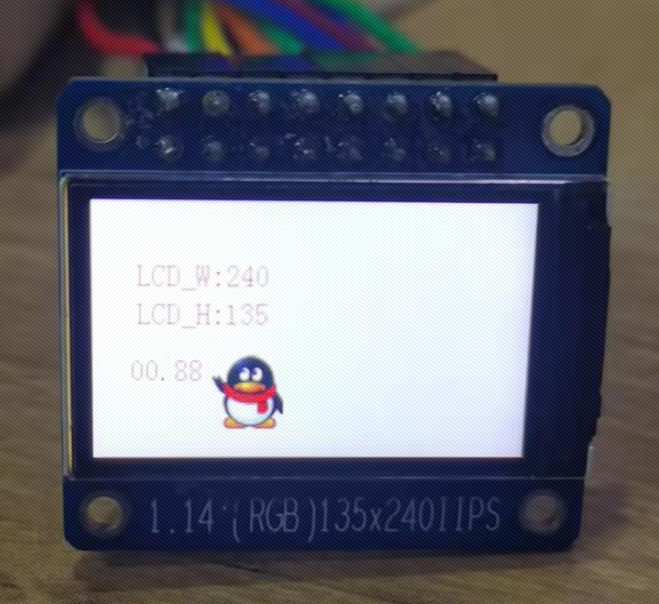
/* * Change Logs: * Date Author Notes * 2024-06-18 LCKFB-LP first version */#include "board.h"#include "stdio.h"#include "bsp_uart.h"#include "lcd_init.h"#include "lcd.h"#include "pic.h"int32_t main(void){ board_init(); // Development board initialization uart1_init(115200); // Serial port 1 baud rate 115200 LCD_Init();//LCD initialization LCD_Fill(0,0,LCD_W,LCD_H,WHITE); float t = 0; while(1) { LCD_ShowString(24,30,(uint8_t *)"LCD_W:",RED,WHITE,16,0); LCD_ShowIntNum(72,30,LCD_W,3,RED,WHITE,16); LCD_ShowString(24,50,(uint8_t *)"LCD_H:",RED,WHITE,16,0); LCD_ShowIntNum(72,50,LCD_H,3,RED,WHITE,16); LCD_ShowFloatNum1(20,80,t,4,RED,WHITE,16); t+=0.11; LCD_ShowPicture(65,80,40,40,gImage_1); delay_ms(1000); }}Power-on phenomenon:
Successful Porting Case(Software and Hardware SPI):
Link:httpshttps://pan.baidu.com/s/1zTC7CuOYCD9DVVJn-VvYPw?pwd=LCKF
Extraction Code: LCKF
ENDPrevious ReviewsREVIEW
【Product Application】CW32 Electric Tool Product Open Source
【Product Solution】Low-Cost Electric Tool Solution Based on CW32L010
【Product Application】Smart Power Bank Based on CW32 (Open Source Solution)
【Product Application】CW-W88 General Control Board Design Scheme (Open Source)
【Product Application】Controller Product Solution for Angle Grinder Based on CW32
【Product Solution】Low-Voltage Brushless Fan Sensorless Controller Based on CW32F030C8
【Product Solution】Brushless DC Hollow Cup Motor Sensor Control Drive Solution Based on CW32
【Product Solution】Brushless DC Hollow Cup Motor Sensorless Square Wave Control Drive Solution Based on CW32
【Product Solution】Digital Voltage and Current Meter Product Solution Based on CW32F003E4P7
【Product Solution】Low-Cost Industrial Instrument Based on CW32L010
CW32 Ecological Community (WX) Group
 Scan to Join QQ GroupGroup 4| 478586307
Get materials and“Developer Support Program”First-Hand Information