Using STM32 Timer to Trigger SPI Communication with DMA
When working on SPI applications, we sometimes want to trigger SPI transmission and reception periodically using a timer and utilize DMA for data transfer. Here, I will demonstrate this based on the STM32L476 chip for reference (the choice of STM32L476 is not particularly special, I just happened to find a Nucleo board).
The general process of this example is as follows:
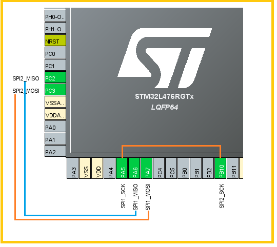
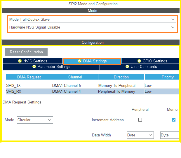
On-chip SPI1 acts as the Master and SPI2 as the Slave, both operating in full-duplex mode.
Here, we use the on-chip timer TIM3 to trigger DMA requests through its update event, transferring data to the data register of SPI1 for sending, while also enabling DMA transmission for the SPI1 reception event. In short, both the reception and transmission events of SPI2 are completed using DMA.
The update event cycle of TIM3 controls the transmission rhythm of the two SPIs, meaning that each time the timer generates an update event, the SPI1/SPI2 communication modules perform one data transmission. We can adjust the timing cycle of the timer to change the speed of data transmission.
First, initialize the configuration based on STM32CubeMx.
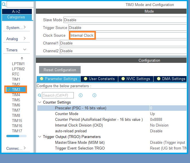
1. Basic configuration for TIM3. Choose the clock source and roughly estimate a timer timing cycle; we can adjust it flexibly during debugging.
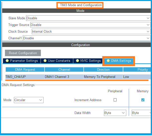
Enable DMA configuration based on the TIM3 update event. The transfer direction is from Memory to peripheral SPI1, meaning transferring memory data to the data register of SPI1 for data sending, using circular mode for testing.
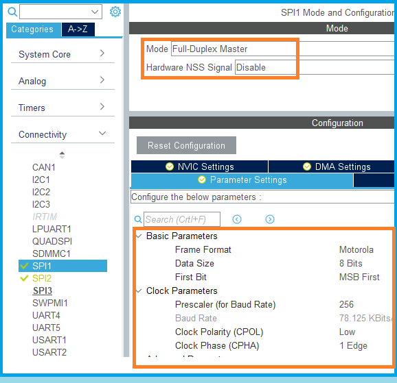
2. Basic configuration for SPI1/SPI2. For details, please refer to the three screenshots below.
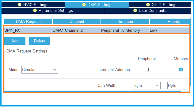
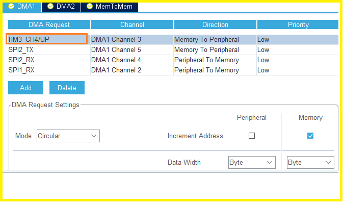
3. DMA configuration.
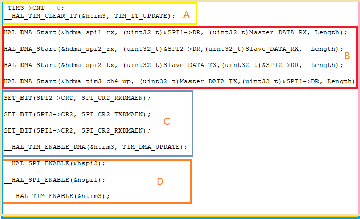
In the TIM3 and SPI1/SPI2 peripheral configurations, the relevant event DMA requests have been enabled, summarized as shown in the diagram below.
4. Prepare user code.
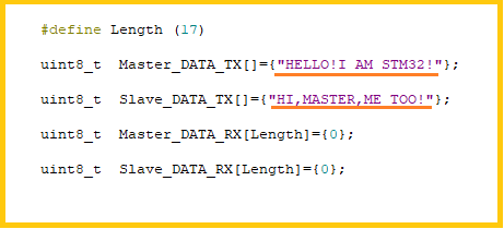
After completing the initialization configuration based on STM32CubeMx and generating the initialization code, we prepare the corresponding user code. Here, four memory arrays are prepared to store the transmission and reception data of SPI1/SPI2.
Under the trigger of the timer, Master SPI1 sends “Hello! I AM STM32!” to Slave SPI2 one byte at a time, and Slave SPI2 responds one byte at a time with “HI, MASTER, ME TOO!”, thus performing a loop operation. The following two screenshots show the user code used in this example, which is written based on the STM32Cube firmware library. It is straightforward and does not require much explanation.
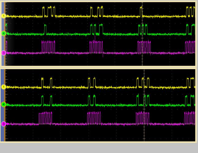
5. Result verification.
The following screenshot shows the signal waveform of SPI communication at two different times. The purple line represents the clock signal, while the green and yellow lines represent the data signals. The time interval between the two data signals is determined by the timer’s update cycle.
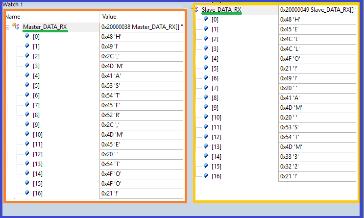
The following screenshot shows the data received by SPI1/SPI2 from each other during the debugging state, where SPI2 received “HELLO, I AM STM32!” and SPI1 received “HI, MASTER, ME TOO!”.
Overall, the implementation of the above application is not difficult, but it may be slightly comprehensive.
To achieve the above application, we must first have a clear understanding of the principles of DMA transmission, including triggering events, transmission sources, and targets, as well as their relationships.
Moreover, even if we develop based on the STM32 firmware library, we may not find complete existing examples; we may need to organize the user program ourselves based on the existing driver code.
Additionally, in the example code above, I did not enable the DMA interrupt events. In specific applications, we can decide whether to enable DMA interrupts based on the situation, such as enabling transfer complete interrupts, etc.
Finally, a reminder: when specifying the source and destination of DMA based on timer event requests, ensure that the DMA triggered by the event can reach the specified location. It is advisable to check the chip data sheet for the chip module and bus framework diagram before programming design; otherwise, you may encounter situations where the specified DMA does not operate normally.