1. Design Concept:
Initially, power is supplied to the microcontroller via a manual switch. The power indicator LED4 lights up, indicating that the microcontroller is running and relay 2 is activated to supply power to the microcontroller. By pressing the button, the working time of relay 2 can be set to achieve automatic power-off, and by setting the working time of relay 1, the fan can rotate intermittently for energy saving.
1. Display Section: By pressing the button, you can switch between the fan rotation time, pause time, and the remaining time until the system shuts down. The digital display shows two digits for “minutes,” while the remaining shutdown time is displayed in “hours.” The LEDs are red, yellow, and blue, indicating the states of fan rotation, pause, and remaining shutdown time, respectively.
2. Button Section:
l K1 is the time adjustment shift key. When this key is pressed, the digital display flashes, and the corresponding light also flashes. It allows switching between fan rotation time, pause time, and system shutdown.
l K2 is the increment and state switch display key. When K1 is pressed, it adds 1 to the time. Otherwise, it switches the display between fan rotation time, pause time, and system shutdown.
l K3 is the decrement and standby key. When K1 is pressed, it adds 1 to the time; otherwise, it has no effect.
3. Relay Section:
l Relay 1 controls the power line of the fan, enabling its rotation and pause.
l Relay 2 controls the power supply of the microcontroller system, enabling timed shutdown of the system.
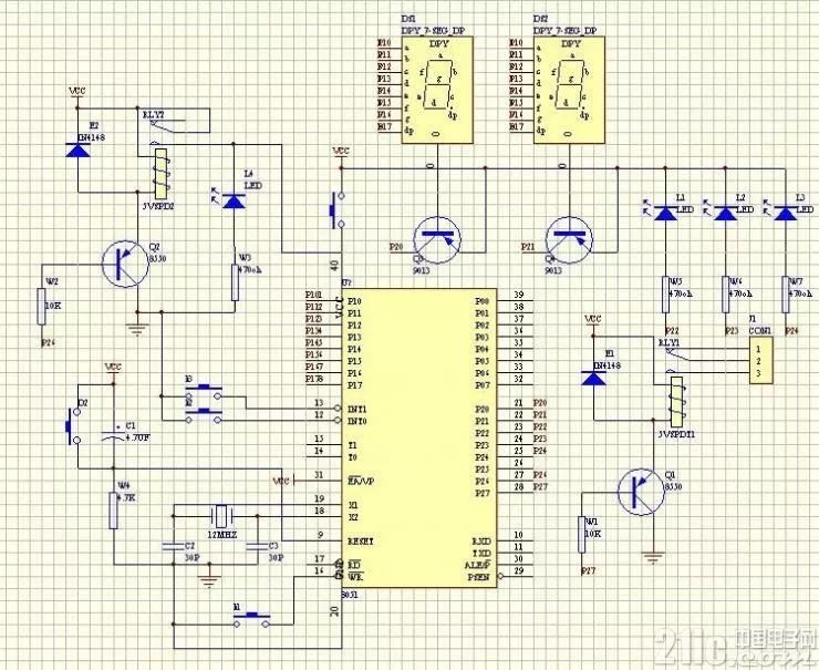
2. Schematic
3. Program Listing
/*********************************************
System Name: Simple Timer Controller for Fan
Creator: w418781840 Date: 2008.7.6
System Functions:
**********************************************/
/*********************************************
Function Name: Declaration Area
Function Description:
**********************************************/
#include
#define uchar unsigned char
#define uint unsigned int
#define SEG P0 // Segment selection for the digital tube.
#define DIG P2 // Digit selection for the digital tube.
uchar dis[2]; // Digital drive group
uchar code TAB[]={ 0xC0,0xF9,0xA4,0xB0,0x99,//0-4 common anode.
0x92,0x82,0xF8,0x80,0x90,0xff};//5-9, off symbol
uchar start,stop,close,sum,time; // Various basic variables
uchar fliflag,cflag,zflag,x,y;// Various flags
uint count_T0,count_T1,c_count; // Counting variables
sbit K1=P3^7; // Function shift key
sbit K2=P3^2; // Increment key and switch key.
sbit K3=P3^3; // Decrement key.
sbit RLED=P2^2; // Red LED, indicates fan rotation status.
sbit YLED=P2^3; // Yellow LED, indicates fan pause status
sbit BLED=P2^4; // Blue LED, indicates system status
sbit CLED=P2^6; // Fan control bit
sbit ZLED=P2^7; // System operation control bit
/*********************************************
Function Name: Delay 1MS Function
Function Description: Display call.
**********************************************/
void delay1ms(uchar x)
{
uchar i,j;
for(i=0;i< x;i++) for(j=0;j<120;j++);
}
/*********************************************
Function Name: Display Function
Function Description: Display minutes, two-digit display.
**********************************************/
void display(void)
{
uchar i,scan=1;
for(i=0;i<2;i++)
{ SEG=0xff;
DIG=~scan;
SEG=TAB[dis[i]];
delay1ms(5);
scan<<=1;
}
}
/*********************************************
Function Name: Delay 5MS Function
Function Description: Key debounce call.
**********************************************/
void delay5ms(uchar x)
{
uchar j;
for(j=0;j< x;j++) display();
}
/*********************************************
Function Name: Initialization Function
Function Description: Initialize various variables.
**********************************************/
void init()
{ fliflag=0;// Flicker flag.
cflag=1; // Fan state flag.
zflag=0; // Rotation flag.
x=30; // Temporary storage
y=10; // Temporary storage
CLED=1;// System working.
sum=0; // Shift
start=30; // Fan rotation time
stop=10; // Pause time.
close=5; // Remaining time until system shutdown
count_T0=0; // T0,T1 related
count_T1=0;
c_count=0;
TMOD=0x11;
TH0=(65536-50000)/256;
TL0=(65536-50000)%256;
TH1=(65536-50000)/256;
TL1=(65536-50000)%256;
EA=1;
ET0=1;
ET1=1;
TR0=1;
}
/*********************************************
Function Name: Separate Function
Function Description: Separate display of tens and units
**********************************************/
void disnner(void)
{ if(cflag==1)//1
{ RLED=0;YLED=1;BLED=1;// Red LED flickers.
time=start; // Display rotation time.
}
if(cflag==2)
{ RLED=1;YLED=0;BLED=1;
time=stop;
}
if(cflag==3)
{ RLED=1;YLED=1;BLED=0;
time=close;
}
dis[0]=time/10;
dis[1]=time%10;
}
/*********************************************
Function Name: T0 Interrupt Function
Function Description: Generate 1 minute.
**********************************************/
void timer0(void) interrupt 1
{ TH0=(65536-50000)/256;
TL0=(65536-50000)%256;
if(++count_T0==1200)// One minute.
{ count_T0=0;
if(zflag==0) // If 0
{ ZLED=1; // Then rotate.
if(start!=99)// If rotation time is 99, display 99, do not switch flag. Keep rotating.
{
start–; // Otherwise, countdown.
if(start==0)
{ zflag=1;// Countdown time reached. Switch flag.
cflag=2;
start=x;// Reassign value
}
}
}
else
{ ZLED=0; // Otherwise pause.
stop–; // Countdown counting.
if(stop==0)
{ cflag=1; // Time’s up.
zflag=0;
stop=y;
}
}
if(close!=99)// If system time is 99, display 99, the system keeps working..
{ if(++c_count==60) // Count 60 for one minute, that is, after one hour.
{ c_count=0;
close–; // Do a one-hour countdown.
if(close==0) // Time’s up, system power off.
CLED=0; // Low level effective.
}
}
}
disnner();// Separate. Send display/
}
/*********************************************
Function Name: T1 Interrupt Service Function
Function Description: Used for adjusting time flicker.
**********************************************/
void timer1(void) interrupt 3
{
TH1=(65536-50000)/256;
TL1=(65536-50000)%256;
if(++count_T1==6)// Flicker period 30MS
{
count_T1=0;
fliflag=~fliflag; // Switch
if(fliflag==0) // Flag effective.
{
if(sum==1)cflag=1;// Use state flicker.
if(sum==2)cflag=2;
if(sum==3)cflag=3;
disnner(); // Used for flickering.
dis[0]=10; // Place off symbol.
dis[1]=10;
}
else // Otherwise, normal display.
{
RLED=1;YLED=1;BLED=1;
dis[0]=time/10;
dis[1]=time%10;
}
}
}
/*********************************************
Function Name: Key Scan Function
Function Description: Adjust time
**********************************************/
void scanner(void)
{ if(K1==0) // If 0, indicates a key is pressed.
{
delay5ms(100);// Delay 500MS.
if(K1==0) // Still pressed. Just released.
{
while(K1==0)display();// Wait for release.
delay5ms(2); // Debounce.
cflag=1; // Exit display state 1.
count_T0=0;
TR0=1; // Start T0
TR1=0; // Turn off flicker
sum=0; // Reset.
x=start; // Temporary storage.
y=stop; // Temporary storage.
}
else
{ // Otherwise, a shift key is pressed.
TR0=0; // Stop time movement.
TR1=1; // Start flicker.
sum++; // Shift.
if(sum==4)
sum=1;
}
}
if(K2==0)
{
delay5ms(2);
if(K2==0)
{
while(K2==0)display();
delay5ms(2);
if(sum) // If there is a shift
{ if(sum==1)
{
start++;
if(start==61)
start=99;
if(start==100)
start=30;
}
if(sum==2)
{
stop++;
if(stop==61)
stop=5;
}
if(sum==3)
{
close++;
if(close==9)
close=99;
if(close==100)
close=1;
}
}
else // No shift.
{
cflag++; // Then perform display state shift.
if(cflag==4)
cflag=1;
}
}
}
if(K3==0)
{
delay5ms(2);
if(K3==0)
{
while(K3==0)display();
delay5ms(2);
if(sum==1)
{ start–;
if(start==29)
start=99;
if(start==98)
start=60;
}
if(sum==2)
{ stop–;
if(stop==4)
stop=60;
}
if(sum==3)
{ close–;
if(close==0)
close=99;
if(close==98)
close=8;
}
}
}
}
/*********************************************
Function Name: Main Function
Function Description:
**********************************************/
main()
{
init();
while(1)
{
display();// Display
scanner(); // Detect key..
}
}