Back in 1989, when I couldn’t afford an oscilloscope but really wanted one, I searched through all the bookstores in the county and finally found a schematic for making an oscilloscope using a television. After building it, I used it for many years.
Now, finished oscilloscopes are everywhere, and I don’t know which mouse has turned that old schematic into a mattress, but with the deep-rooted memory of making an oscilloscope in my mind, I have redrawn the original schematic and would like to share it, hoping it will help enthusiasts.
The principle of this oscilloscope is based on utilizing the electromagnetic signal radiation and reception of a television. The adapter does not connect to the television; instead, both communicate through electromagnetic interference signals, so the television remains unmodified (the input signal line of the adapter is placed next to the horizontal deflection coil).
Principle: The television oscilloscope adapter receives the horizontal retrace pulse signal and uses it as a synchronization signal, then generates a noise signal controlled by the waveform being measured, which is then received by the television. The adapter does not have a synchronization circuit for the measured signal; it stabilizes the waveform by adjusting the frame rate on the television. 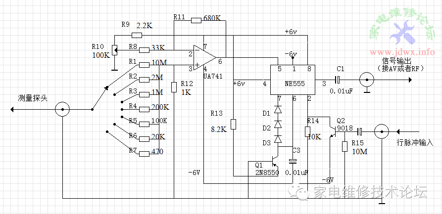
This oscilloscope can be made using a black-and-white television with a screen size of up to 8 inches, and it displays quite well; even old CRT color TVs can show the output. It has accompanied me and helped me repair many devices, including amplifiers, Toshiba rocket launchers, and Panasonic picture kings, until I got an AnTaiXin 7328. If you’re interested, it’s worth a try.
Original text:http://www.jdwx.info/thread-559345-1-1.html
Additionally, here’s a PS image of the oscilloscope. 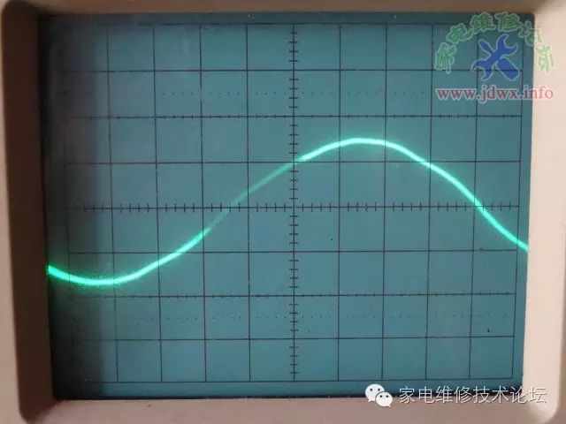
▼ Follow us on WeChat ▼
Home Appliance Repair Technology Forumjdwx-cn

▲ Long press the QR code to follow