STM32 UART Communication
This article documents the problems and summaries encountered during my learning process. UART communication plays a significant role in the actual use of STM32 in various scenarios. This article provides a brief summary of UART communication.
1. UART Communication in STM32
In STM32, UART communication is implemented through USART. STM32 can transmit parallel data via UART with full-duplex and asynchronous clock control, allowing point-to-point transmission between devices. The corresponding STM32 pins are RX and TX. STM32 has several UART resources: USART1, USART2, USART3.
Some important parameters of UART:
-
Baud rate, the speed of UART communication.
-
Idle, generally high level.
-
Start bit, marks the beginning of a data frame, fixed as low level. A falling edge occurs when data starts to be sent. (Idle -> Start bit)
-
Data bits, the data frame being sent, 1 for high level, 0 for low level. Low bits are sent first. For example, sending the data frame 0x0F results in low bit linear representation as 1111 0000.
-
Parity bit, used for data validation, calculated based on data bits. There are odd parity, even parity, and no parity.
-
Stop bit, used for data spacing, fixed as high level. A rising edge occurs after the data frame is sent. (Data transmission -> Stop bit)
Below is the transmission process of one byte of data. As shown in the figure, the data sent via UART is generally transmitted in the form of data frames, each consisting of a start bit, data bits, and stop bits, with variable stop bits.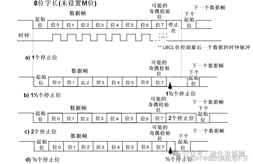
2. Sending and Receiving Data via UART
USART is a hardware peripheral integrated within STM32, which can automatically generate data frame timing based on one byte of data in the data register and send it out through the TX pin. It can also automatically receive data frame timing from the RX pin and assemble it into one byte of data stored in the data register.
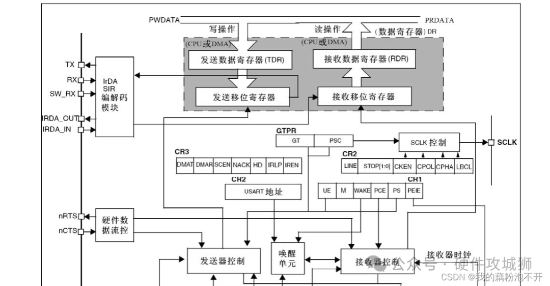
Once the USART circuit is configured, data can be automatically sent and received by directly reading the data register. There are four important registers in the sending and receiving module:
-
Transmit Data Register (TDR)
-
Shift Register for sending data, shifts one byte of data out bit by bit.
-
Receive Data Register (RDR)
-
Shift Register for receiving data, shifts one byte of data.
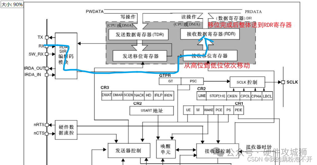
Below is a diagram illustrating the sending and receiving of UART data:
Sending Data via UART
When configuring various parameters of the UART, one can choose the size of the data bits for the data frame to be sent, either 8 bits or 9 bits.
Sending data via UART is essentially a write operation to the Transmit Data Register (TDR).
1. When sending data via UART, it checks whether the Shift Register has data shifting. If not, the data will immediately transfer to the Shift Register and prepare for sending.
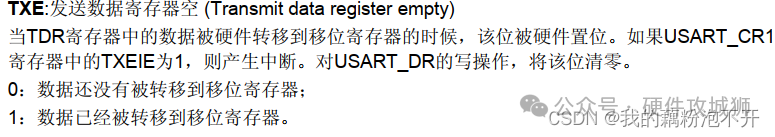
2. When data moves to the Shift Register, a TXE (Transmit Data Register Empty) flag is set. This flag indicates whether the next data can be written into TDR. If TXE is set to 1, the next data can be sent.
3. The Shift Register under the control of the transmitter shifts right, transmitting data bit by bit to the TX pin.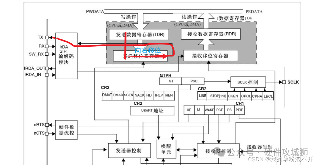
4. Once data shifting is complete, new data will again be transferred from TDR to the Shift Register, repeating steps 1-3. The TXE flag indicates whether the next data can be sent.
Receiving Data via UART
-
Data flows from the RX pin to the Shift Register for receiving data, reading the RX level bit by bit under the control of the receiver. The first bit is placed in the highest bit, and after shifting right eight times, one byte can be received.
-
Once the byte of data is shifted completely, it will move as a whole to the Receive Data Register (RDR).
-
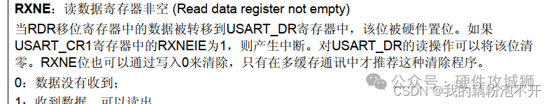
During the transfer, the RXNE (Receive Data Register Not Empty) flag is set, indicating that the RDR register is not empty. Below is the description of this flag. When set to 1, it indicates that data can be read.
 Below is the workflow for UART receiving.
3. Configuring UART in STM32
First, clarify a few points: which UART peripheral of STM32 to use? Is it for sending or receiving data? What are the UART-related parameter configurations? Will interrupts be used for sending or receiving?
Below is the configuration for sending data via UART.
1. RCC enables the clock for USART and the corresponding GPIO for TX/RX.
RCC_APB1PeriphClockCmd(RCC_APB1Periph_USART2,ENABLE);  // Enable clock for USART2
RCC_APB2PeriphClockCmd(RCC_APB2Periph_GPIOA,ENABLE);   // Enable clock for GPIOA
2. Initialize the GPIO port. Note that the GPIO port should be configured according to your needs, whether both sending and receiving are required or just one. Then initialize the corresponding GPIO port according to the pin definition table.
The pins corresponding to USART2:
The pins corresponding to USART1:
Here, according to the manual, set the RX pin mode to floating input or pull-up input. The TX pin mode is set to alternate push-pull output.
**For example, I only initialize the TX sending end**
//TX pin
    GPIO_InitTypeDef GPIO_InitStructure;
    GPIO_InitStructure.GPIO_Mode=GPIO_Mode_AF_PP;  // Alternate push-pull output
    GPIO_InitStructure.GPIO_Pin=GPIO_Pin_2;   // The TX pin for USART2 is GPIOA2
    GPIO_InitStructure.GPIO_Speed=GPIO_Speed_50MHz;  // 50MHz
    GPIO_Init(GPIOA,&GPIO_InitStructure);
3. Initialize the UART. Note that the USART_Init() function is used to configure the related parameters of the UART.
-
USART_BaudRate is the baud rate used for UART communication, typically 9600 or 115200. Here we set it to 9600.
-
USART_HardwareFlowControl indicates whether to use hardware flow control, which we generally do not select, so we choose no hardware flow control.
-
USART_Mode is an important parameter. It specifies whether the UART is in transmission mode, reception mode, or both.
-
USART_Parity is for parity bits, which can be odd, even, or none. If no requirement, select no parity.
-
USART_StopBits indicates the number of stop bits, which can be 1, 0.5, or 2. Here we choose 1 stop bit.
-
USART_WordLength indicates the data bits, which can be 8 or 9 bits.
 // UART initialization
	USART_InitTypeDef USART_InitStruct;
	USART_StructInit(&USART_InitStruct);  // Initialize to default values
	USART_InitStruct.USART_BaudRate=9600;
	USART_InitStruct.USART_HardwareFlowControl=USART_HardwareFlowControl_None;   // No hardware flow control
	USART_InitStruct.USART_Mode=USART_Mode_Tx;    // TX transmission mode
	USART_InitStruct.USART_Parity=USART_Parity_No;   // No parity
	USART_InitStruct.USART_StopBits=USART_StopBits_1;   // 1 stop bit
	USART_InitStruct.USART_WordLength=USART_WordLength_8b;  // 8 data bits
	USART_Init(USART2,&USART_InitStruct);
4. Enable the UART.
// Enable the UART
   USART_Cmd(USART2,ENABLE);
5. Sending data via UART. Note that we need to check the status of the TXE flag. 0 means data has not yet been transferred to the Shift Register; 1 means data has been transferred to the Shift Register and can be sent.
void Serial_SendByte(uint16_t Byte)
{
	USART_SendData(USART2,Byte);
	// 0 indicates data has not been transferred to the Shift Register; loop until 1 means data has been transferred and can be sent
	while(USART_GetFlagStatus(USART2,USART_FLAG_TXE)==RESET);  // No need to manually clear; it will be automatically cleared when writing to TDR again
}
After the above five configurations, the microcontroller can send data via UART.
Below is a diagram of sending data, where STM32 sends the data 0x16: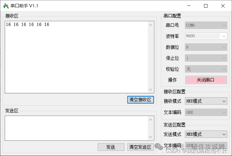
4. Two Methods for Receiving Data via UART
Above is the example for sending data. How should we configure receiving data via UART, and what changes need to be made to the sending example?
We can receive data using either polling or interrupt methods.
-
The polling method involves continuously checking the RXNE flag by determining its status to ascertain whether data has been received.
-
The interrupt method involves configuring the receive output control channel, setting up NVIC, and handling data reception in the interrupt service routine.
1. Changes Needed
Since we want to implement UART reception, we need to configure the RX pin and add the USART_Mode_RX mode in the UART configuration.
-
Initialize the RX pin.
//RX pin
	GPIO_InitStructure.GPIO_Mode=GPIO_Mode_IPU;  // Pull-up input
	GPIO_InitStructure.GPIO_Pin=GPIO_Pin_3;
	GPIO_InitStructure.GPIO_Speed=GPIO_Speed_50MHz;  // 50MHz
	GPIO_Init(GPIOA,&GPIO_InitStructure);
-
Add UART mode.
USART_InitStruct.USART_Mode=USART_Mode_Tx|USART_Mode_Rx; // TX transmission mode, RX reception mode
2. Polling RXNE Flag
Let’s take a look at the description of the RXNE flag:
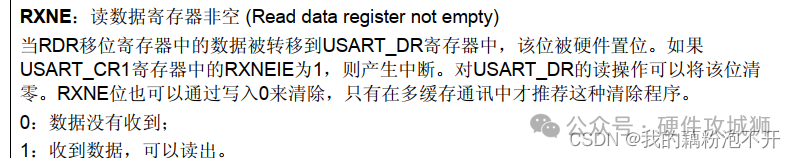 The image shows that when it is 0, data has not been received; when it is 1, data has been received and can be read from RDR.
Thus, in the main program, continuously read the RXNE flag. If it is 1, it indicates data can be read.
uint8_t RX_Data;
int main()
{
	Serial_Init();
	Serial_SendByte(0x16);
	while(1)
	{
		if(USART_GetFlagStatus(USART2,USART_FLAG_RXNE)==SET)   // 0 means loop waiting; 1 means data can be received
		{
			RX_Data=USART_ReceiveData(USART2);
			Serial_SendByte(RX_Data);
		}
	}
}
Below is the program phenomenon: the PC sends data 0x15 to the microcontroller, which receives the data 0x15 and sends it back to the PC, displaying 0x15 on the PC: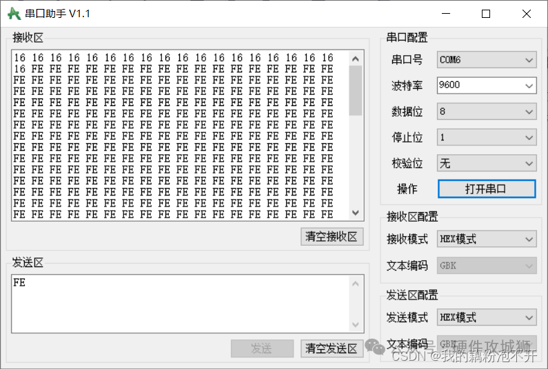
3. Using Interrupts
-
Configure the UART reception as an interrupt source, enable interrupt output control, and configure NVIC to enable the interrupt channel.
// Enable interrupt output control
	USART_ITConfig(USART2,USART_IT_RXNE,ENABLE);

	// Configure NVIC
	NVIC_PriorityGroupConfig(NVIC_PriorityGroup_2);
	NVIC_InitTypeDef NVIC_InitStruct;
	NVIC_InitStruct.NVIC_IRQChannel=USART2_IRQn;   // Select USART2 interrupt channel
	NVIC_InitStruct.NVIC_IRQChannelCmd=ENABLE;      // Enable interrupt
	NVIC_InitStruct.NVIC_IRQChannelPreemptionPriority=1;
	NVIC_InitStruct.NVIC_IRQChannelSubPriority=1;
	NVIC_Init(&NVIC_InitStruct);
-
Once the interrupt service routine is properly written, you can read the received data within the interrupt. When data is received, it triggers the receive interrupt, pausing the main program until the data is received, after which the main program resumes execution.
void USART2_IRQHandler(void)
{
	if(USART_GetITStatus(USART2,USART_IT_RXNE)==SET)   // RXNE flag is 1, indicating data can be received
	{
		RX_Data=USART_ReceiveData(USART2);
		Flag=1;
		USART_ClearITPendingBit(USART2,USART_IT_RXNE);  // Clear RXNE flag
	}
}
-
Main program testing.
uint8_t RX_Data;
uint8_t Flag;

int main()
{
	Serial_Init();
	Serial_SendByte(0x16);


	while(1)
	{
		if(Flag==1)
		{
			Serial_SendByte(RX_Data);
		}
	}
}

void USART2_IRQHandler(void)
{
	if(USART_GetITStatus(USART2,USART_IT_RXNE)==SET)   // RXNE flag is 1, indicating data can be received
	{
		RX_Data=USART_ReceiveData(USART2);
		Flag=1;
		USART_ClearITPendingBit(USART2,USART_IT_RXNE);  // Clear RXNE flag
	}
}
Below is the program phenomenon: it can be seen that the UART indeed received data. I placed the received data 0xFE in the while loop, indicating that data reception was successful and the use of interrupts is feasible.
Conclusion
In conclusion, we have summarized the sending and receiving of data via UART.
UART configuration can use polling or interrupts to receive data.
UART is commonly used, so this summary serves as a review and consolidation of previous knowledge, reinforcing the concepts.
Source: https://gitcode.csdn.net/65e6e6b81a836825ed787581.html
— End —
How to Configure HAL Library in STM32
Detailed Explanation of External Interrupts in STM32 (Principle + Configuration Code)
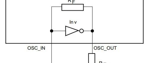
Design and Matching of External Crystal Oscillator Circuit in STM32
Complete Startup Process of STM32
👇 Focus on Sharing Valuable Electronics Hardware Content 👇