Article Summary
This article analyzes twisted pair Ethernet using a mixed-signal oscilloscope as the analytical tool, delving into the encoding of two common types of twisted pair Ethernet. It also examines and verifies the signal transmission of Ethernet at the physical layer, concluding with a practical example comparing the data received by software in an actual network with the signals captured by the oscilloscope. This article bridges the gap between hardware and software, revealing the mechanisms of Ethernet data transmission from the physical layer while fully utilizing the bus decoding capabilities of modern mixed-signal oscilloscopes.
The content of this article mainly includes:
■ 1. Overview of Ethernet
■ 2. 10 Base-T Ethernet
■ 3. 100 Base-TX Ethernet
3.1 4B5B
3.2 MLT-3
3.3 NRZ-I
3.4 Example
3.5 Practical Application
■ 4. Conclusion
■ References
1. Overview of Ethernet
Ethernet is a common computer networking technology, with its technical standards defined in IEEE 802.3 [1]. Currently, widely used Ethernet exchanges information through twisted pair cables (commonly known as network cables), with its technical standards primarily specified in TIA/EIA-568 [2].
This article uses the most common Ethernet standards as examples, utilizing the protocol decoding capabilities of mixed-signal oscilloscopes to unveil how signals are transmitted over Ethernet. Typically, network data analysis is performed on software, such as the well-known Wireshark tool, which can capture and parse data transmitted over a specified network interface [3]. However, such operations obscure the differences at the physical layer; this article goes further to reveal how data is specifically transformed into electrical signals and transmitted at the physical layer.
Ethernet (10 Base-T) and Fast Ethernet (100 Base-TX) can use the same twisted pair for data transmission, with the pin definitions shown in Figure 1.
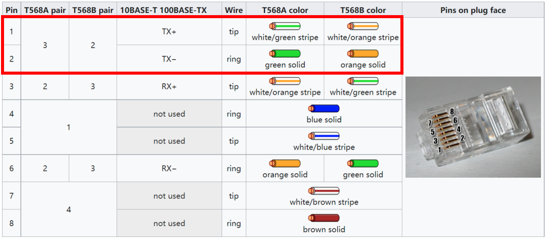
Figure 1. Pin definitions of the network cable [1]
Taking T568B as an example, it uses 4 wires to form 2 differential pairs (TX and RX). Without loss of generality, we take one pair (TX) as the analysis object. Therefore, we need to connect Pin 1 and Pin 2 to the oscilloscope probes to capture the signals. Here, we cut open a network cable and connect a wire to Pin 1 and 2, creating a dedicated jumper for analysis, as shown in Figure 2.
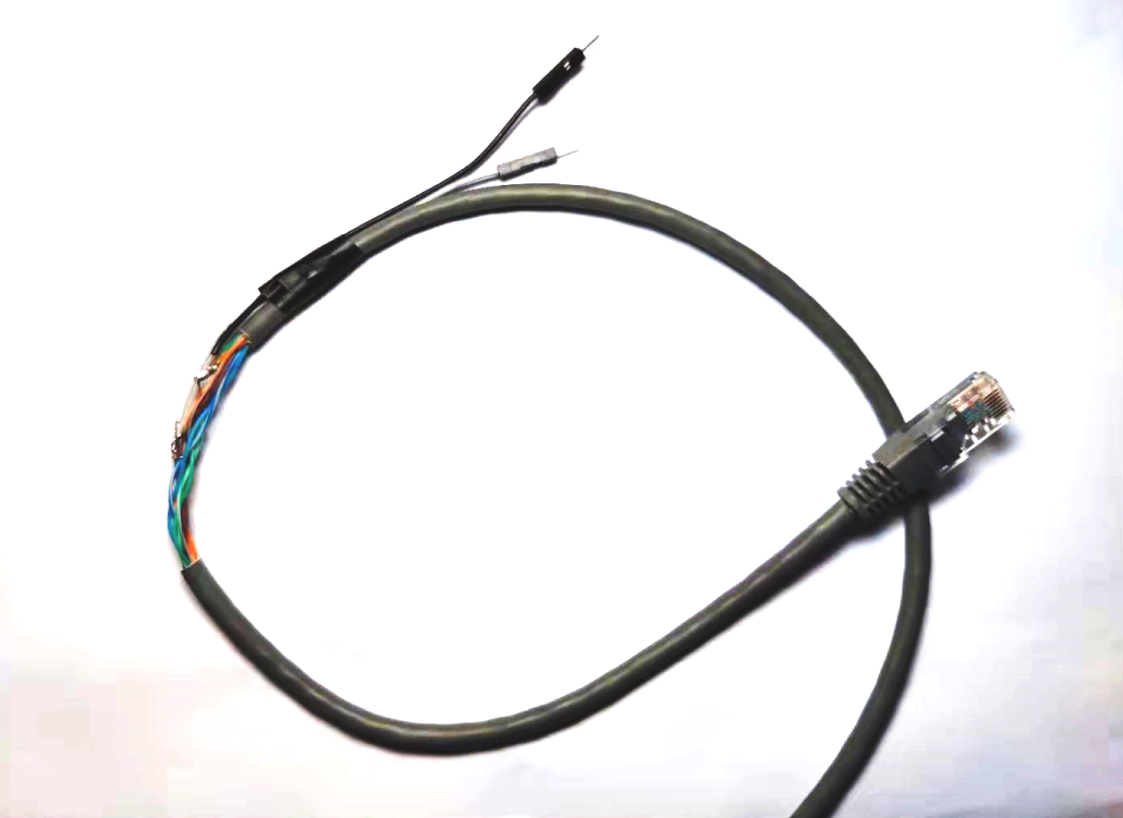
Figure 2. Connecting a wire to Pin 1 and 2 of the twisted pair
This pair transmits differential signals, so it is best to use a differential probe (e.g., TDP1500). Of course, since the jumper used here is relatively short, a regular passive probe can also be used, although the signal quality may be somewhat affected.
For practical measurement explanations, see here👇
(If you think the video is good,
please like, follow, and share~)
2. 10 Base-T Ethernet
The transmission rate of 10 Base-T is 10 Mbps, using Manchester encoding (phase encoding) for data. “0” is represented by a falling edge, and “1” is represented by a rising edge.Figure 3 shows a segment of the differential waveform captured by the oscilloscope. After confirming the minimum pulse width, the direction of the periodic edges can be used to identify “0” or “1”.
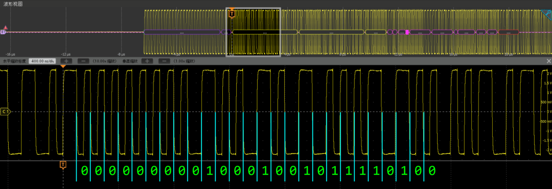
Figure 3. Manchester encoding analysis of 10 Base-T
Next, the binary sequence needs to be assembled into a data frame. Due to the stacking of multiple protocols (MAC, IP, TCP, etc.), manual decoding can be quite complex; the oscilloscope’s bus decoding tool can be used directly for decoding and display. As shown in Figure 4, set the bus to “Ethernet” and the speed to “10 Base-T”, with the signal type set to “differential”, and other options can be selected based on actual conditions or left as default.

Figure 4. 10 Base-T decoding settings
The decoding result is shown in Figure 5, where an IPv4 data frame can be seen, and upon zooming in, the MAC address and other specific contents within the data packet can be observed.
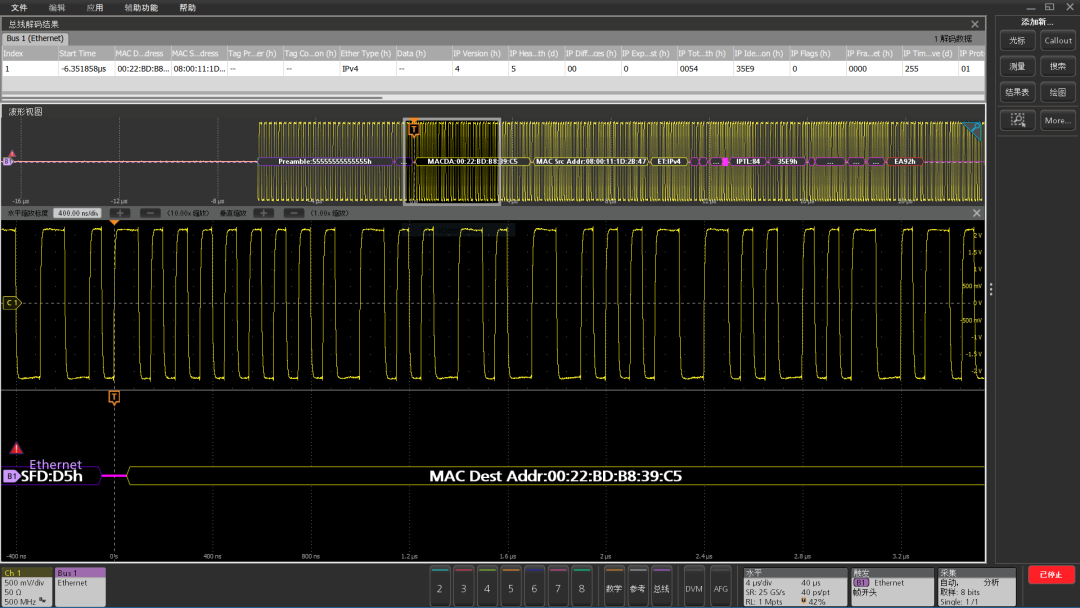
Figure 5. Decoding results of 10 Base-T
3. 100 Base-TX Ethernet
Compared to 10 Base-T, 100 Base-TX offers a tenfold speed increase, reaching 100 Mbps. Its encoding protocol has also become significantly more complex, mainly involving three keywords: 4B5B, MLT-3, and NRZ-I.
3.1
4B5B
4B5B represents the use of 5-bit binary encoding to represent a group of 4 bits of data [4]. The reason for this is to ensure that there are enough transitions on the transmission line to recover the clock. The encoding rules of 4B5B are predefined, and if only decoding is needed, a lookup table can be used, as shown in Figure 6. For example, if “0000” or “1111” were transmitted directly, it would result in four identical codes, likely introducing a strong DC component. However, after 4B5B encoding, they become “11110” and “11101”, alleviating this issue. The downside of 4B5B is that it requires an additional 25% transmission bandwidth, so while the data transmission rate of 100 Base-TX is 100 MBps, it requires a clock frequency of 125 MHz.
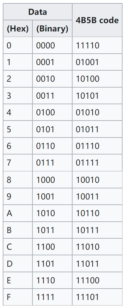
Figure 6. 4B5B correspondence table
3.2
MLT-3
MLT-3 stands for “Multi-Level Transmit”, which uses multiple voltage levels to transmit data [5]. MLT-3 uses three voltage levels, which can be normalized on the differential transmission line as “-1”, “0”, and “+1”. MLT-3 achieves transitions by switching voltages, following two rules:
(1) If the voltage before the transition is -1 or +1, the voltage after the transition is 0;
(2) If the voltage before the transition is 0, the voltage after the transition is the opposite of the last non-zero voltage.
Thus, the transition sequence can be simply summarized as: -1 → 0 → +1, or +1 → 0 → -1.
3.3
NRZ-I
MLT-3 describes the rules for voltage transitions but does not specify the relationship between voltage transitions and data “0” or “1”. NRZ-I stands for “Non-Return-to-Zero Inverted”, meaning that a “0” does not transition, while a “1” does.
3.4
Example
Combining the three keywords mentioned earlier, the electrical signal change rules for 100 Base-TX can be summarized as follows:
100 Base-TX first encodes every 4 bits of data into 5-bit binary using 4B5B encoding; then it uses three voltage levels to transmit data. If the data is “0”, the voltage does not change; if the data is “1”, the voltage changes once, always transitioning in the opposite direction of the historical level, such as -1 → 0 → +1, or +1 → 0 → -1.
Finally, 100 Base-TX does not transmit the signal itself directly but rather the XOR result of the signal and the scrambler, as shown in Figure 7. The captured signal is first decoded according to the MLT-3 rules, grouped into sets of five bits, marked in green font. Next, the descrambler (scrambler key) sequence is found. The scrambling is not encryption; it is merely used to improve electromagnetic characteristics, so both scrambling and descrambling require only XOR operations using the same sequence. 100 Base-TX uses an 11-bit linear feedback shift register (LFSR) to generate a 2047-bit long pseudo-random sequence. This makes it very difficult to manually find the synchronization point, but if the program automatically synchronizes, it becomes very easy. The descrambled data is grouped into sets of 5 bits, and by looking up the 4B5B encoding table, we can obtain the data in groups of 4 bits. Figure 7 shows the encoding analysis results of three bytes.
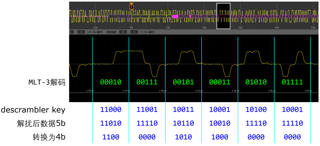
Figure 7. Encoding analysis of 100 Base-TX
Although manual decoding of 100 Base-TX is very complex, with the help of the oscilloscope’s bus decoding tool, decoding can be completed very quickly and conveniently. The oscilloscope settings are shown in Figure 8. Since it is a standard protocol, there are not many options; set the bus to “Ethernet”, the speed to “100 Base-TX”, the signal type to “differential”, and other options can be selected based on actual conditions or left as default.

Figure 8. 100 Base-TX decoding settings
Decoding results are shown in Figure 9.
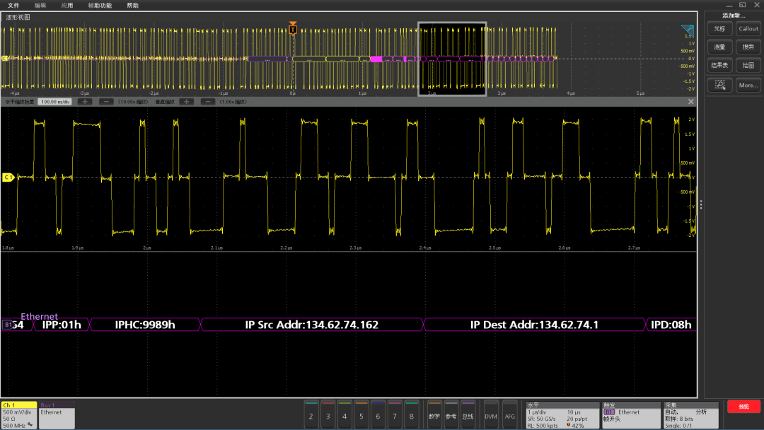
Figure 9. Decoding results of 100 Base-TX
The decoding process of 100 Base-TX is complex, with a large amount of data, making retrieval inconvenient. Typically, protocol analysis software is needed for further analysis. Now, mixed-signal oscilloscopes have integrated decoding and analysis functions, requiring only a special network cable to complete all analysis work, thoroughly displaying the Ethernet transmission mechanism on the screen.
3.5
Practical Application
We set up a small local area network with two computers and conducted a ping operation for practical verification. By capturing with Wireshark, we can see several ping request and reply packets on the network interface, as shown in Figure 10. On the TX differential pair, we should find the outgoing ping request packet, with a source address of 192.168.0.2 and a destination address of 192.168.0.1.
On the oscilloscope, we set the Ethernet bus decoding and configured the trigger to the specified IP. As shown in Figure 11, the trigger position is set to “IP header”, with the source address set to “192.168.0.2”, so when a data packet with the specified source address appears, the oscilloscope will be triggered.
As shown in Figure 12, this is the data packet captured and decoded by the oscilloscope after the above settings, which, upon comparison, is consistent with the data captured by the software in Wireshark.
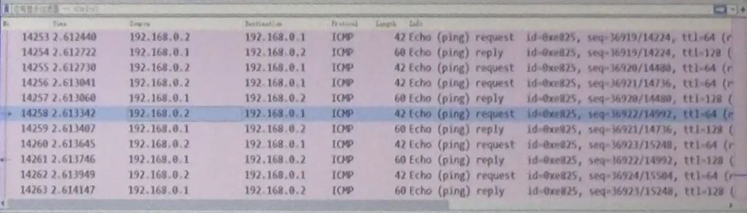
Figure 10. Wireshark captured ping request and reply packets
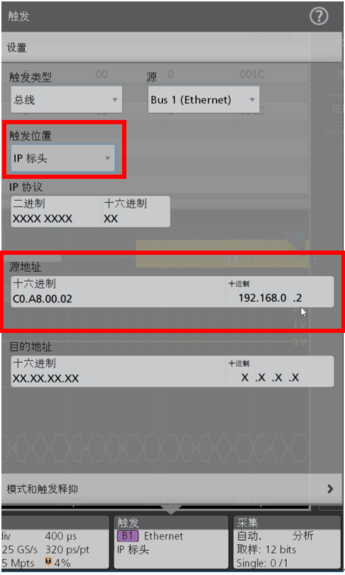
Figure 11. Trigger set to specified IP
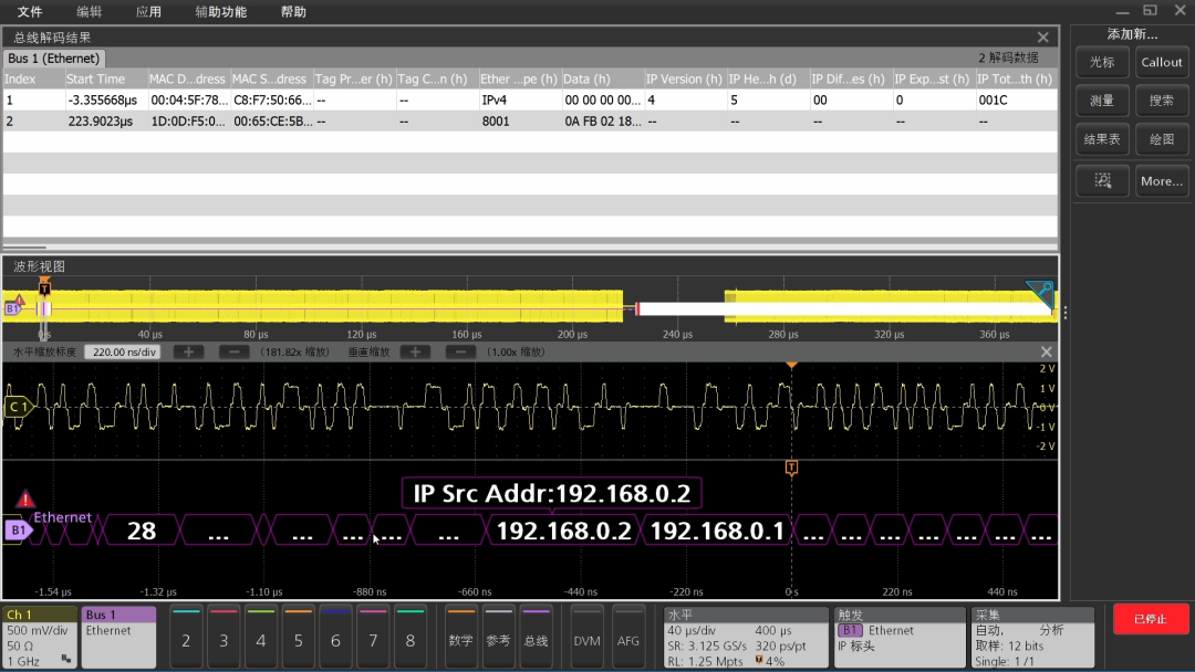
Figure 12. Data packet captured and decoded by the oscilloscope
4. Conclusion
There are always some gaps between software and hardware. For example, in Ethernet analysis, the traditional computer networking field mainly introduces the design and implementation of the logical link layer and higher layers from a software perspective, with relatively simple introductions to the physical layer. Conversely, the traditional hardware field often only introduces simple serial buses for digital signals and does not take more complex Ethernet as an example.
This article deeply analyzes the encoding of two common types of twisted pair Ethernet and utilizes the bus decoding capabilities of mixed-signal oscilloscopes to examine and verify the signal transmission of Ethernet at the physical layer. Finally, through a practical example, it compares the data received by software in an actual network with the signals captured by the oscilloscope, revealing the mechanisms of Ethernet data transmission from the physical layer.
References
[1] https://en.wikipedia.org/wiki/Ethernet
[2] https://en.wikipedia.org/wiki/ANSI/TIA-568
[3] https://www.wireshark.org
[4] https://en.wikipedia.org/wiki/4B5B
[5] https://en.wikipedia.org/wiki/MLT-3_encoding
Click Read the original text to learn more technical content!
For more product and application details, you can also contact us through the following methods:
Email: [email protected]
Website: www.tek.com.cn
Phone: 400-820-5835(Monday to Friday 9:00-17:00)


Turn Your Inspiration into Reality
We provide professional measurement insights aimed at helping you improve performance and turn various possibilities into reality. Tektronix designs and manufactures solutions that help you test and measure, breaking through the barriers of complexity and accelerating your global innovation pace. Together, we can help engineers at all levels create and achieve technological advancements more conveniently, quickly, and accurately.


Click “Read the original text” to learn more!