01
What made me curious about passive probes
It all started with a question: can a 1X passive probe be used to match a 50-ohm or 75-ohm system like a coaxial cable? Experienced individuals would immediately say no, because even a 1X probe has a significant resistor in series. I happened to have a broken probe on hand, so I measured the internal resistance with a multimeter, and it was over 300 ohms! The outer conductor, however, measured a normal fraction of an ohm. Clearly, this “coaxial cable” cannot be used to match a 50-ohm or 75-ohm system.
The problem seems to be solved, but it deepens my curiosity about passive probes: why is there such a large resistor in series, and why does a 1X probe have a much lower bandwidth than a 10X probe?
02
Disassembling a probe to see what’s inside
Disassembling this passive probe is quite challenging; the overall injection-molded structure is particularly hard, making it impossible to use water mouth pliers to gradually peel off the plastic. After removing the plastic shell, there is a metal sleeve inside, which cannot be clamped further. After much effort and a few injuries, I finally managed to disassemble this device:
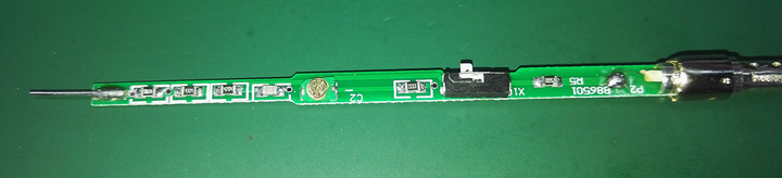
It consists of a probe, a circuit board, several resistors and capacitors, a single-pole double-throw switch, and a coaxial cable, just like that.
The circuit looks like this:
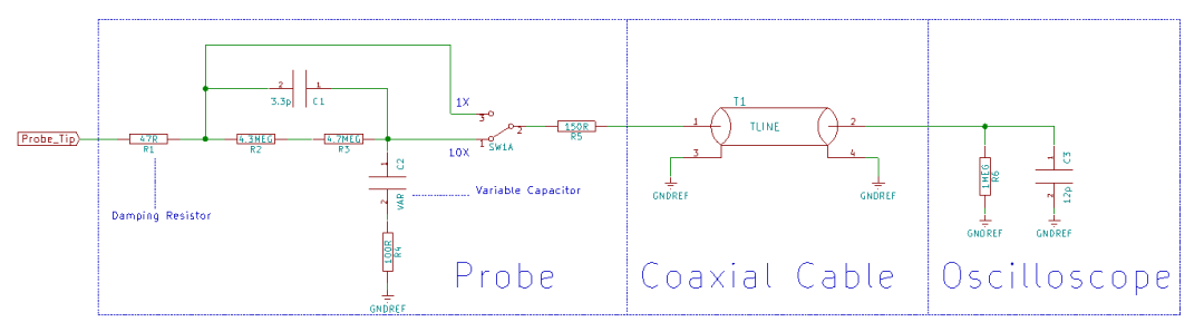 Equivalent circuit diagram of the passive probe
03
Damping resistor on the probe
Indeed, there is a significant resistor in series with the probe, but why is such a resistor necessary? Let’s do a simple modeling simulation:
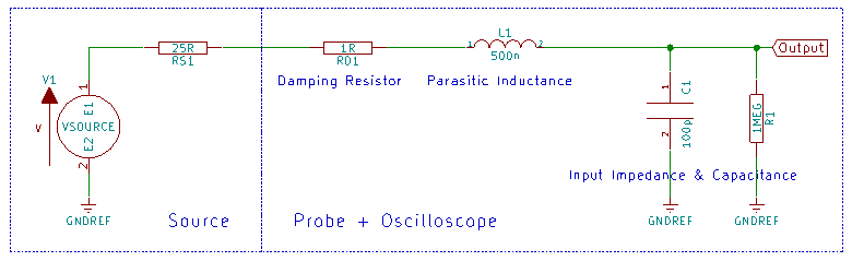
Here, RS1 is the source resistance, taken as an empirical value of 25 ohms; RD1 is the input damping resistor of the passive probe, which will be varied during the simulation; L1 is the parasitic inductance of the probe cable, taken as an empirical value of 500nH; C1 is the sum of the parasitic capacitance of the probe cable and the input capacitance of the oscilloscope, also taken as 100pF based on experience; R1 is the input impedance of the oscilloscope, which is 1M ohm.
By varying the value of RD, we can scan values of 1, 25, 50, 75, 100, 150, and 200 ohms, and the system’s frequency response and step response are as follows:
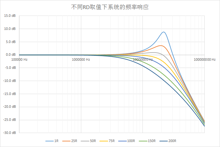
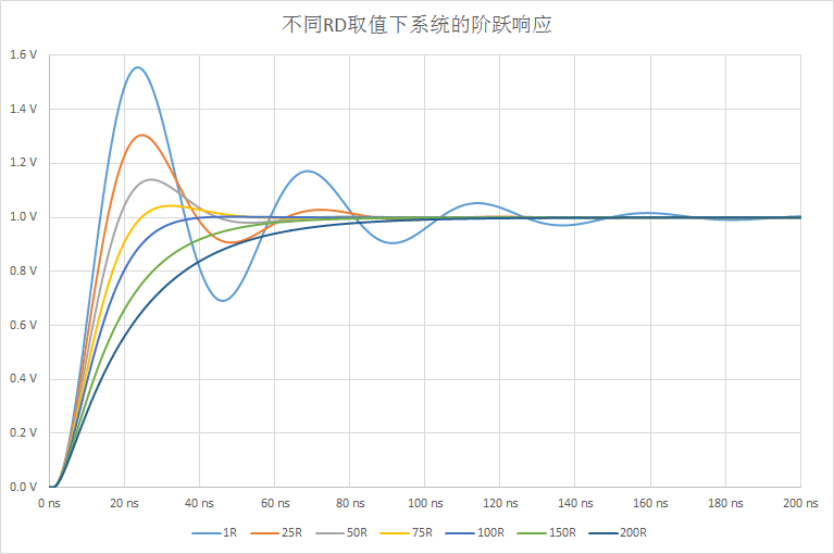
The main function of this damping resistor is to counteract the peaks in the system frequency response caused by the parasitic inductance of the probe. If the damping resistor is too small, the peaks will be significant, and the time-domain waveform will exhibit large overshoots. If the damping resistor is too large, it will lead to insufficient system bandwidth. The actual value is often a compromise based on the characteristics of the probe and the oscilloscope, determined through tuning.
04
Why does a 10X probe have a higher bandwidth than a 1X probe?
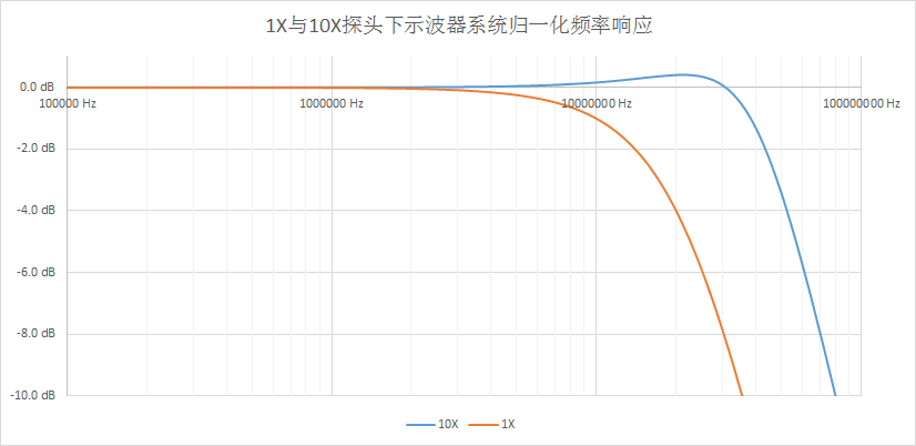
As seen in the previous section, due to the presence of parasitic capacitance and inductance and the damping resistor, the bandwidth of the system under a 1X probe is relatively low. However, a 10X probe can achieve a higher system bandwidth by adding a compensation circuit in the attenuation network. The simplified system model is as follows:
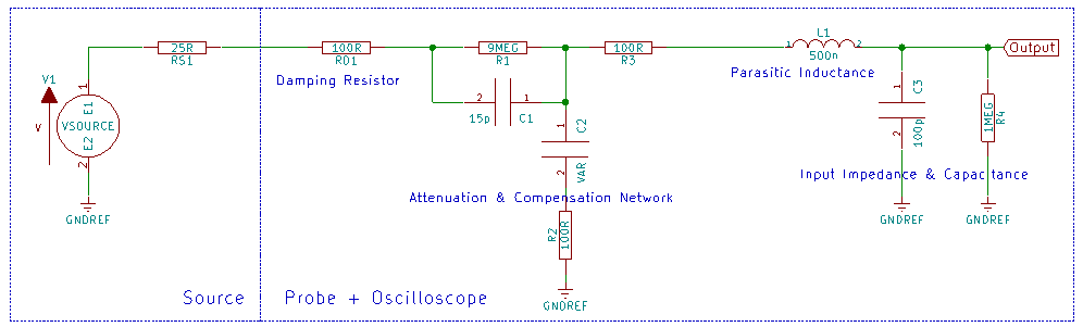
Here, the damping resistor RD1 is set to 100 ohms, and the bandwidth under 1X is approximately 17MHz. A compensation network is connected in series between the damping resistor and the parasitic inductance of the probe cable, where C2 is an adjustable capacitor (remember that compensation knob on the probe?). By appropriately adjusting the values of C1, C2, R2, and R3, an ideal system frequency response can be achieved.
Of course, the real situation is much more complex than this model. Friends who have used high-bandwidth passive probes should notice that, in addition to adjusting the low-frequency (1kHz square wave) adjustable point (which is C2 here), high-bandwidth probes also have one or two adjustment points for high-frequency compensation (possibly R2 and R3 here) to adjust for high-frequency overshoot.
05
Not your typical coaxial cable
Having explored the components of the probe, let’s return to the initial question: can a 1X passive probe be used to match a 50-ohm or 75-ohm system like a coaxial cable? The answer is no, because there is a large damping resistor in series with the probe. So, if I cut off the probe (which is quite expensive, so it pains me to do this) and use the remaining coaxial cable to match a 50-ohm or 75-ohm system, would that work? Few people can answer this correctly.
First, let’s take this piece of coaxial cable to a VNA and see what the results are.
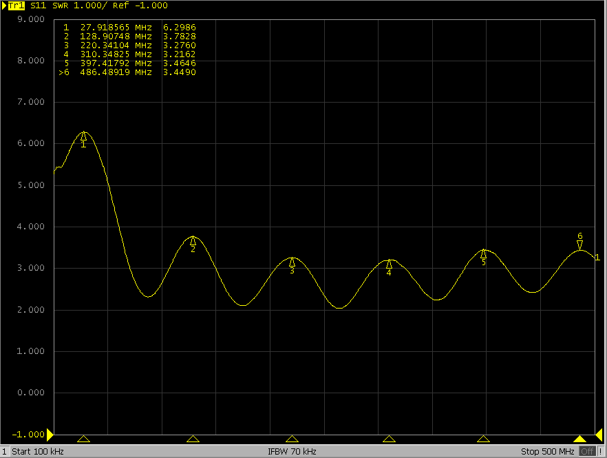
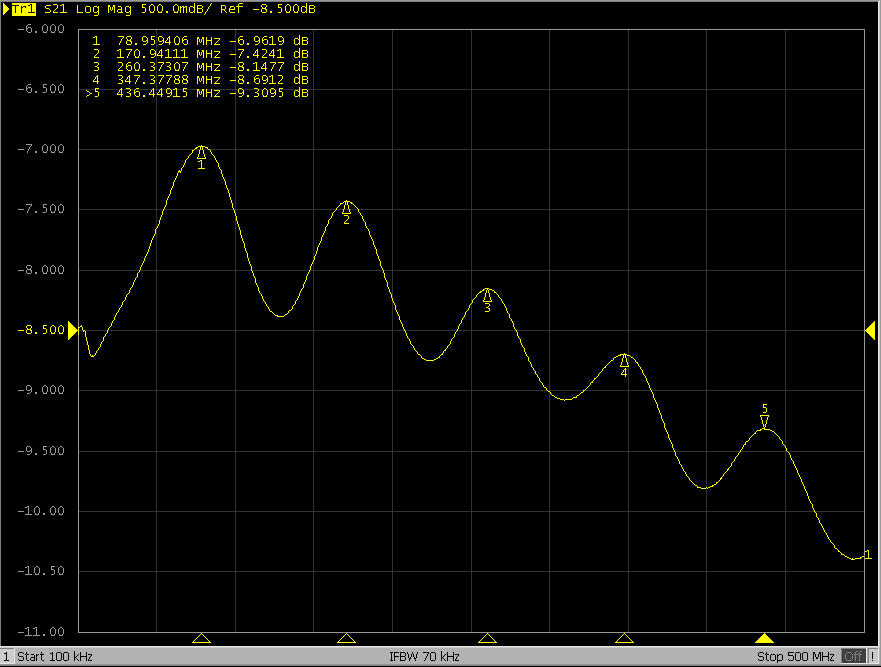
What the heck?! It doesn’t look like a coaxial cable at all. I measured several times, ruling out VNA faults, calibration issues, improper testing methods, and broken coaxial cables… it really looks this ugly.
At this point, careful readers may notice that I initially measured the internal resistance of the probe core to be over 300 ohms, but in the simplified schematic of the probe, the damping resistor is less than 200 ohms, right? Did I lose over 100 ohms in this coaxial cable? Yes, indeed, measuring the resistance of this coaxial cable core, which is over 1 meter long, surprisingly shows nearly 180 ohms of resistance.
Such a high resistance is certainly not due to a faulty cable; there must be a reason for its existence. Without further ado, let’s check it with TDR.
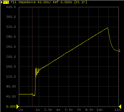
A diagonal line indicates that the impedance is uniformly distributed along the cable. Is this the legendary impedance taper? However, it is somewhat different from a typical impedance taper, as this line has a particularly high insertion loss due to a significant resistive component.
In a system composed of a source, a passive probe, and an oscilloscope, with an unknown source impedance and a terminal impedance of 1M ohm, how should the probe’s transmission line be matched to this system? Perhaps it would be better not to match it at all, and instead use a high-loss transmission line to reduce reflections; it’s that simple and crude. (I am not too familiar with RF, so I am unsure if this statement is correct; I hope readers will point out any inaccuracies.)
Source: Zhihu Author: Jiang Yuchen

Disclaimer:
This account maintains neutrality regarding all statements and opinions in original and reprinted articles. The articles are provided for readers’ learning and communication purposes. Copyright for articles, images, etc., belongs to the original authors.
Submissions/Recruitment/Promotion/Advertising please add WeChat: 15989459034