The address-specified write function supports EMMC_AUTO_ISP (flying line programming), EMMC_AUTO (offline 8x programming), EMMC_AUTO_4BIT (offline socket 4x programming), and EMMC_AUTO_1BIT (offline socket 1x programming).
The operation methods for several programming modes are the same, and we will take EMMC_AUTO as an example to introduce the “custom address writing” function. After selecting the EMMC_AUTO function, click on “Settings” on the left side, which will pop up a small box containing 5 setting areas (see Figure 2.32). Here, we will briefly introduce the settings interface.
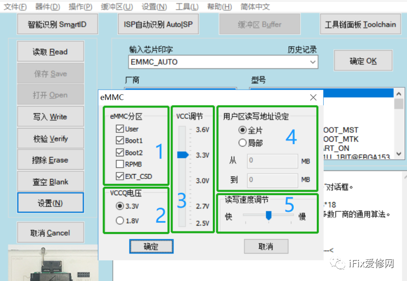
(Figure2.32)
The first area is the EMMC partition read/write settings. There are a total of 5 partitions in EMMC: User area (User area), BOOT1 area (Boot area), BOOT2 area (Backup Boot area), RPMB area (Hardware Encryption area), and EXT_CSD area (Extended Register). In the maintenance of the TV motherboard, the RPMB area is rarely used, so by default, only the User area, Boot area, Backup Boot area, and Extended Register are checked.
If you are very familiar with the motherboard chip scheme, you can set it manually. Generally, Mstar chip schemes only have files in the boot1 area and User area. MTK, RTD, Amlogic, and HISI only have files in the User area.
For Mstar chip schemes, writing files to the boot1 area and user area is sufficient; for non-Mstar chip schemes, only writing the User area file is needed.
The local EMMC storage chip does not need to be written; when replacing the EMMC, it is necessary to write the EXT_CSD file. If the EXT_CSD file is not written, the system may not boot.
Conclusion: If you are very familiar with the motherboard chip scheme, you can manually set the partition read/write according to the chip scheme; if not familiar, you can directly read and write according to the default settings.
The second area is the VCCQ voltage setting, which is only selected during flying line reading/writing. The VCCQ voltage of the EMMC on the motherboard can be either 3.3V or 1.8V. It is crucial to select the correct VCCQ voltage during flying line reading/writing; for offline, just select 3.3V.
The third area is VCC voltage adjustment, used during offline operations. Some aging chips require backups, necessitating an increase or decrease in VCC voltage to achieve data reading.
The fifth area is the read/write speed selection, which defaults to standard read/write mode. Technicians can select the read/write speed according to their computer performance.
The fourth area is the custom address segment read/write. This function is considered an excellent solution, allowing specified address read/write and erasure, which is of great significance for the repair industry. So what does this mean? Let’s give a few examples.
1. For example, LeEco TV members bind membership through MAC address and SN serial number, which are stored in the first 100M addresses of the User area;
When repairing, if the motherboard is replaced, it is equivalent to losing the membership, requiring re-binding of the membership. At this point, it is necessary to read the original board’s EMMC User area’s first 100M data (see Figure 2.33).
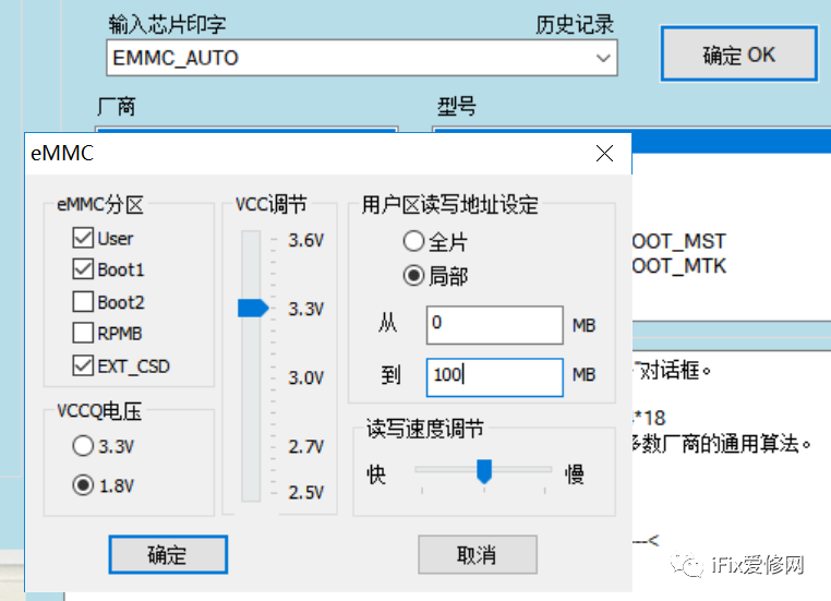
(Figure2.33)
Then use a hex editor to search for the “devicekey” string to find the original MAC and SN information (see Figure 2.34), and with this information, the membership can be re-bound.
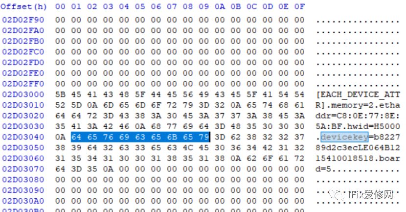
(Figure2.34)
2. If you need to open the serial port information for the Mstar chip scheme offline, and it is known that the serial port flag for a single EMMC is within the first 20M, you can directly read 20M, then search for the “UARTOnOff=off” string in the read content and modify “UARTOnOff=off” to “UARTOnOff=on.” (see Figure 2.35). The modified file can then be written into the EMMC’s 0-20M address segment to open the serial port information.
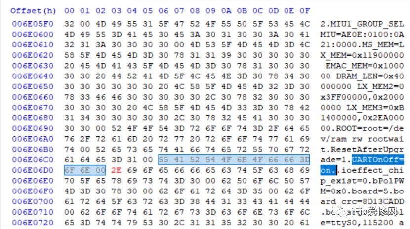
(Figure2.35)
3. If you need to offline write the boot program for the MTK chip scheme, the EMMC’s 0-2M is the MTK boot program address. The size of the boot file for domestic MTK chip schemes is about 1M, while the boot file size for Sharp is about 1.5M. Therefore, when writing the manufacturer’s boot, you can directly set the address segment to 0-2M (see Figure 2.36) and write the manufacturer’s provided bin file.
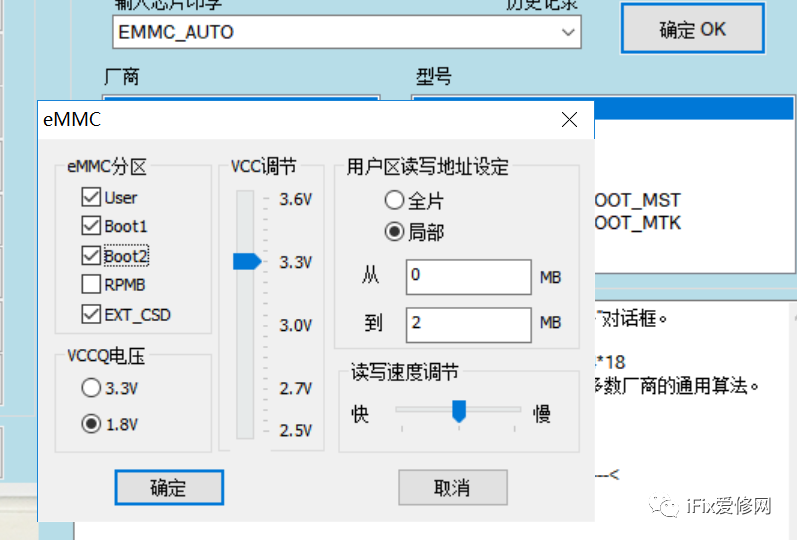
(Figure2.36)
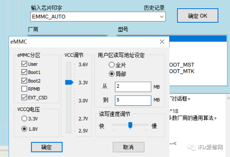
4. If you need to offline write the boot program for the Mstar chip scheme, it is known that the boot files for Mstar single EMMC storage are in the Boot1 area and User area from 2-5M. Therefore, when writing the manufacturer’s boot, directly set the User area read/write address to 2-5M, and then write the manufacturer’s boot file with the correct format name (see the previous RT809H function knowledge, Figure 2.20).
Recently, several chapters mainly introduced the common functions of the RT809H programmer applied to smart TV motherboard repair. Knowing these repair knowledge points is one thing, but applying them is another. It is recommended that everyone practice the operation of the RT809H programmer and apply it in real combat; more and better hidden functions are waiting for you to discover.