Hello everyone, I am Pi Zi Heng, a technician dedicated to technology. Today, I will introduce the NXP i.MX RT1170 uSDHC eMMC boot time.
This is the fifth article in the evaluation series of i.MX RT1170 boot times. The previous four articles evaluated the boot times of Raw NAND (based on MIMXRT1170-EVK_Rev.B), Serial NOR (based on MIMXRT1170-EVB_Rev.A2), 1-bit SPI NOR recovery boot time (based on MIMXRT1170-EVK_Rev.C), and Serial NAND boot time (based on MIMXRT1170-EVKB_Rev.B).
Regarding the SD/eMMC boot enable method for the i.MX RT series, I have written two articles titled “RT600 Boot from eMMC” and “RT1050 Boot from SD”. The methods in these articles are generally applicable to the entire i.MX RT series (with only minor differences). Recently, I have been supporting a customer using the RT1170, who has implemented eMMC boot and sent the board to me for debugging. Taking this opportunity, I will conduct a detailed test of the eMMC boot time on their board:
1. Preparation
1.1 Knowledge Reserve
Aside from the different types of underlying data transmission interface peripherals, the SD/eMMC boot process is almost identical to the Serial NAND/Raw NAND boot process. From the perspective of storage media, both are NAND, so I won’t elaborate further. Please refer to section 1.1 of my previous evaluation articles.
However, it is important to note that the boot devices evaluated earlier (serial and parallel NOR/NAND) have read/write data rate performance close to the interface speed (although NAND has additional ECC verification time). In contrast, SD/eMMC involves bad block management and wear leveling, which incurs additional time overhead in internal processing. Therefore, the actual data read/write rates differ from the data interface speeds, and this difference varies depending on the processing algorithms in the manufacturer’s products; you need to refer to the device chip data manual.
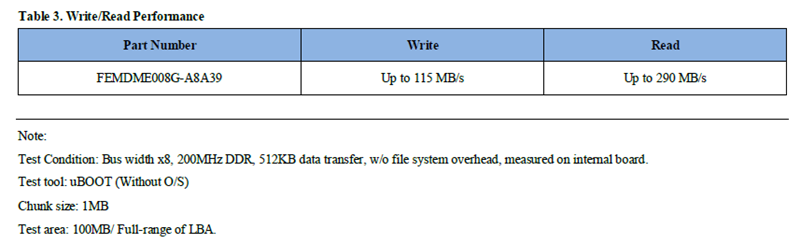
This test used an 8GB capacity chip FEMDME008G-A8A39 from Jiangbolong, compatible with the eMMC 5.1 standard. According to its data manual, the maximum interface speed is 400MBps (HS400 mode), but the actual data read/write rates were 290MBps and 115MBps respectively.
eMMC 5.1 specification compatibility
- Backward compatible to eMMC 4.41/4.5/5.0

Bus mode
- Data bus width: 1 bit (default), 4 bits, 8 bits
- Data transfer rate: up to 400 MB/s (HS 400)
- MMC I/F Clock frequency: 0~ 200 MHz
1.2 Time Definition
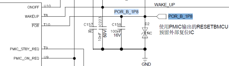
For the starting and ending points of the time measurement, refer to section 1.2 of “FlexSPI NOR Boot Time”. Although this test used the customer’s board, we only need to select the POR_B measurement point as the time starting point.
1.3 Application Program Development
For application program development, refer to section 1.3 of “Serial NAND Boot Time”. In fact, there has been a minor limitation in Non-XIP program development that wasn’t emphasized in previous evaluation articles. Recently, I finally wrote a dedicated article titled “General Link Limitations of Non-XIP Apps” for everyone to understand.
1.4 Application Program Download
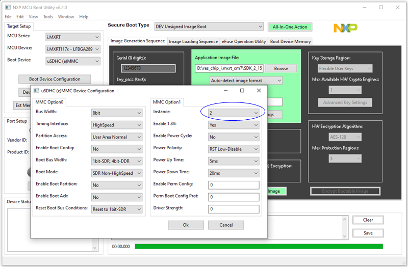
The application program download requires the use of the NXP-MCUBootUtility tool developed by me. Since the 8-bit eMMC is only supported by uSDHC2, customers usually connect eMMC to the uSDHC2 pins. When configuring the eMMC with the tool, the main concern is to ensure the instance is correct. As for the choice of other speed modes, it only relates to the program download speed and does not affect the eMMC boot time.
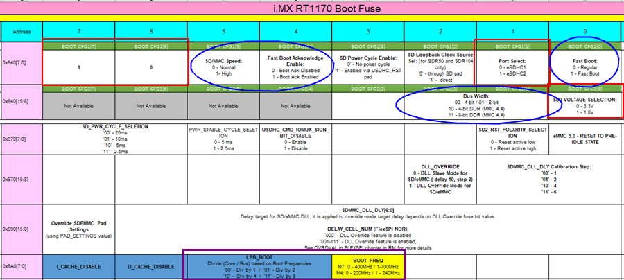
The main factors affecting the eMMC boot time are the configurations in the RT1170 chip fuse, where the options marked in red are mandatory based on hardware conditions, and the options in blue can be chosen by users as per their requirements (these will also be the factors affecting the boot time tested in the next section). The purple box determines the core frequency during BootROM operation; when CM7 is the main core, the default is 400MHz, which can be upgraded to 700MHz. We will not change the default core frequency configuration of BootROM.
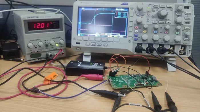
1.5 Oscilloscope Signal Capture
Everything is ready, and we can use the oscilloscope to capture the eMMC boot time. This time, I took a shortcut and measured two signal channels: one channel monitors the main chip’s POR signal, while the other monitors the GPIO signal (this GPIO will be pulled low in the app). Unlike before, this time the GPIO selected is the pin with the BOOT_CFG function, which has an external strong pull-up. There will be additional interesting findings in the next section’s test results summary.
2. Testing Begins
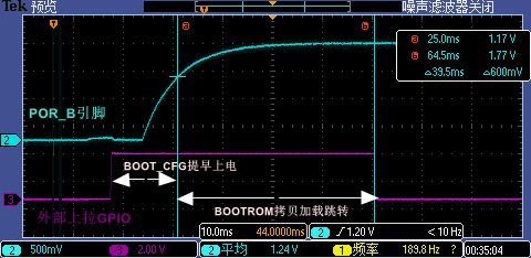
Before announcing the results, let me first analyze the boot time waveform captured by the oscilloscope to help everyone understand the components in the subsequent tables. The voltage rise time of the POR signal is relatively slow, powered by VDD_1V8, and we take the standard effective value of 70% – 1.2V as the time starting point.
Additionally, we can see that the GPIO was already pulled high before the POR signal rose, indicating that the GPIO powered on earlier than the POR, which is consistent with the i.MXRT power-up sampling timing specifications. I have an article titled “If RT Cannot Start Offline, Please Check the SRC_SBMRx Register” related to this point.
2.1 Testing Different App Lengths
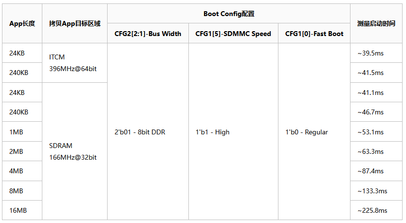
First, we conduct tests related to different App types and lengths, where the Apps are linked in ITCM and SDRAM (the latter requires enabling BootROM DCD initialization). Additionally, due to the large SDRAM space, various App lengths are tested. All tests are conducted under the same Boot Config configuration, which is the configuration used by this customer as indicated in my article “Two-Level Design to Shorten Boot Time for NAND Boot Devices”.
From the test results, the eMMC boot time for Apps under 1MB is similar, showing no significant proportional relationship with App length. Even for Apps under 4MB, no obvious relationship is observed; however, when viewed in units of 4MB, a certain proportional relationship can be seen.
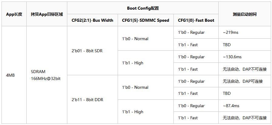
2.2 Testing Different Speed Modes
Since 4MB has certain representativeness for executing Apps in SDRAM, I based my tests on this and tested different combinations of Boot Config configurations. When BOOT_CFG1[0] is set to Fast Boot, it generally fails to start (more configuration may be needed). Under the Regular Boot condition for BOOT_CFG1[0], High Speed is nearly twice as fast as Normal Speed, and 8-Bit DDR is also nearly twice as fast as 8-Bit SDR.
Thus, I have introduced the eMMC boot time for NXP i.MX RT1170. Where is the applause~~~