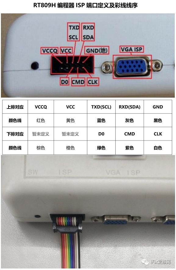
EMMC ISP refers to the flying wire read and write of EMMC chips, communicating by connecting the CMD, CLK, D0, and GND of the EMMC. Due to varying power consumption across different boards, it is recommended that the power supply VCC be provided by the original board, and under this condition, VCC and VCCQ can be left unconnected.
Related options for EMMC ISP include:
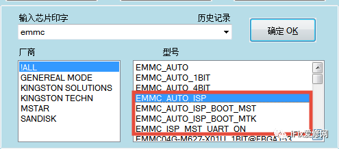
EMMC_AUTO_ISP: Full chip read and write, or read and write by setting partitions;
EMMC_AUTO_ISP_BOOT_MST: MST single EMMC scheme for writing boot programs;
EMMC_AUTO_ISP_BOOT_MTK: MTK single EMMC scheme for writing boot programs;
EMMC_ISP_MST_UART_ON: Opens the serial port for the MST single EMMC scheme, which can solve most of the UART BUS OFF issues;
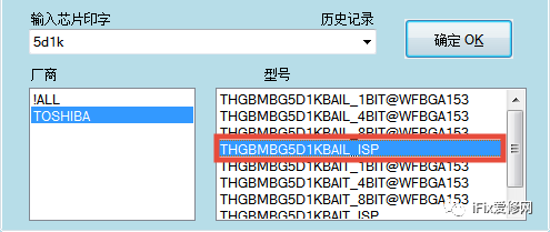
THGBMBG5D1KBAIL_ISP: [EMMC model_ISP] This is chosen for the flying wire read and write of a specific model, while EMMC_AUTO_ISP is applicable to all EMMC chips, and there is no need to distinguish the chip model.
To read and write data from the EMMC chip via flying wire, the following issues need to be addressed:
1.ISP wire length issue: Based on the official colored wire, homemade wires that are too long can lead to chip recognition failures and reading/writing errors.
2.The main control chip must stop working:
(1) Short-circuit the main control chip’s crystal oscillator and then connect it to ground; note that some motherboards have multiple large chips, avoid short-circuiting the wrong crystal oscillator, as this is a common mistake for beginners.
(2) For some main control chips, it may be necessary to disconnect the power supply during standby.
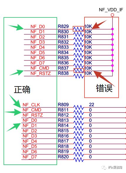
3.Ensure accurate flying wire points: For example, D0 and CMD in the following image are connected to VCCQ power supply through a 10K resistor. On the circuit diagram, most people will not make a mistake in knowing where to connect, but in actual wiring, it is easy to connect the wire to the power supply instead due to the two ends of a single resistor, this is a common error.
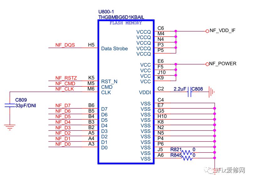
4.Board power supply VCC: Check whether the EMMC power supply is still present when the main control is not working. EMMC versions above 5.0 have both 3.3V and 1.8V (when using HS400 mode), while lower versions only require 3.3V. After completing the flying wire, do not forget to power the board before starting read/write operations.
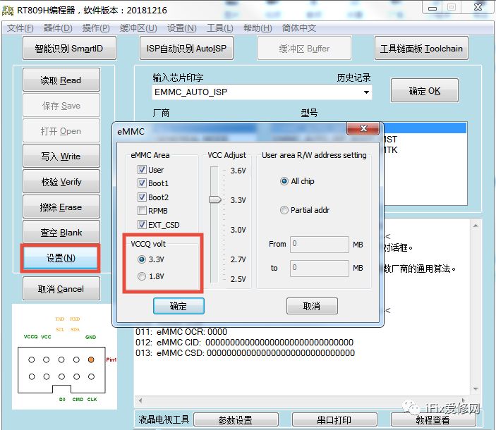
5.VCCQ voltage setting: IO power supply, divided into 3.3V and 1.8V, select and confirm.
6. Interference issues:If it is inconvenient to eliminate interference, it is recommended to use a BGA offline socket.
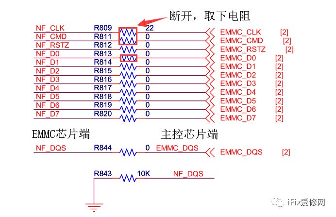
(1) Main control chip: In this case, disconnect the resistors connected to clk, cmd, and d0. If there are no resistors connected, the printed line can be cut;
(2) External interference: Please refer to this link [Is the anti-interference capability of RT809H poor?]
Common phenomena:
Example 1: The customer needs to open the serial port, and the chip’s corresponding ID has been recognized, but writing fails.
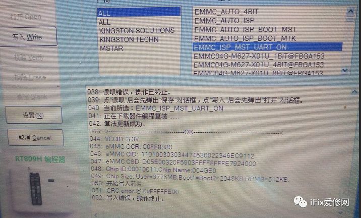
Possible reasons: Interference caused by the main control chip; the chip itself;
Solution: Remind the customer to disconnect all connections between the flying wire and the main control chip, then writing works normally. Initially, the customer only disconnected the CLK connected to the main control chip, and after disconnecting CMD and D0, the problem was resolved.
Example 2: After connecting the flying wire and powering the motherboard, selecting EMMC_AUTO_ISP and clicking read results in the phenomenon: chip not recognized.
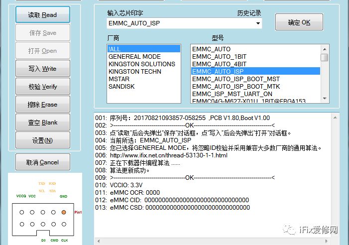
Possible reasons: The board is not powered; the flying wire points are inaccurate; the VCCQ voltage is not set correctly; interference from the main control chip.
Solution: If you forgot to power it on, please connect the power supply; ensure the points are accurate for the flying wire; set the VCCIQ voltage on the left side of the software interface, which is divided into 3.3V and 1.8V; disconnect all connections between the emmc side’s cmd clk d0 and the main control chip, and short-circuit the crystal oscillator to ground, etc.
Example 3: Error occurs after reading/writing to xx%.
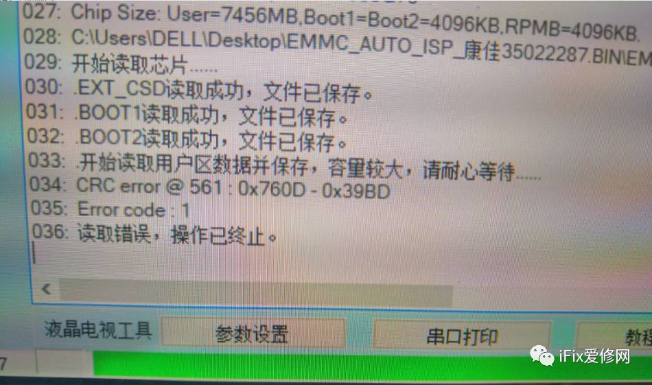
Possible reasons: Interference from the main control chip; external interference; the chip itself.
Solution: Disconnect all connections between the emmc side’s cmd clk d0 and the main control chip, and short-circuit the crystal oscillator to ground, etc.; external interference; if it is a chip issue, consider replacement for verification.
Note the distinction between the following options; they are options for writing the boot program via serial port, where the serial port refers to RX, TX, which can be connected through VGA, HDMI, or ports labeled UART, DEBUG, RX TX, RXD TXD on the board.
MSTAR_EMMC_MBOOT #ISP
MSD6A338_EMMC_MBOOT #ISP
MSD6A628_EMMC_MBOOT #ISP
MSD6A638_EMMC_MBOOT #ISP
MSD6A828_EMMC_MBOOT #ISP
MSD6A918_EMMC_MBOOT #ISP
MSD6A928_EMMC_MBOOT #ISP
The following article details the functions of these options: RT809H New Features Explained.
To enter the course, please long press the QR code in the image below.