Overview of the EMMC Protocol
Whether it’s EMMC V4.5 or V5.1, the protocol can seem overwhelming for newcomers who may struggle to grasp the key points or analyze it properly. This article summarizes some important and commonly used aspects of the EMMC protocol.
1. Basic Understanding of EMMC
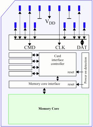
1.1 Physical Connections:

| Physical Interface | Interface Meaning |
|---|---|
| CLK | Clock line, each cycle of this signal controls the transmission of 1 bit on the command line and 1 bit (1x) or 2 bits (2x) on all data lines. |
| CMD | Command line, this signal is a bidirectional command channel used for device initialization and command transmission. CMD signal has two operating modes: open-drain mode for initialization and push-pull mode for fast command transmission. |
| DAT0-7 | These are bidirectional data channels. DAT signals operate in push-pull mode. In the default state, only DAT0 is in push-pull mode, while DAT1-7 are in pull-up (internal pull-up), and after entering 4-bit mode, DAT0-3 are in push-pull mode. |
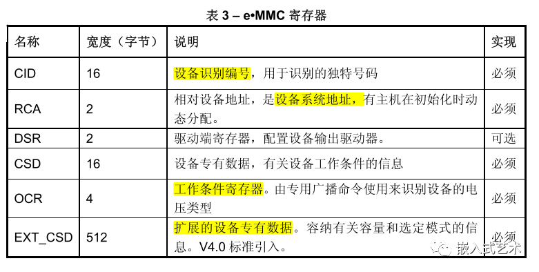
1.2 Understanding EMMC Related Registers
1.3 Understanding Other Features
-
Read/Write Modes: Single block read/write, multiple block read/write
-
Addressing Methods: Byte addressing and sector addressing, byte addressing allows a maximum of 2GB, for capacities exceeding 2GB, sector (512B) addressing is used.
-
Voltage Modes: Supports high voltage and dual voltage modes.
-
Supports enhanced partition modes, etc.
2. Bus Protocol
2.1 Basic Understanding
-
Command: A Token that initiates an operation, sent from the host to the device, transmitted serially on the CMD line. -
Response: A Token sent from the device to the host as a reply to the previous command, transmitted serially on the CMD line. -
Data: Bidirectional transmission between the host and slave, with bus widths of 1-bit (default), 4-bit, and 8-bit.
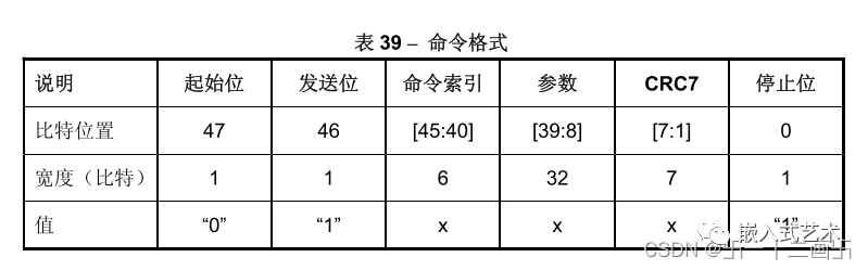
2.2 Command Format
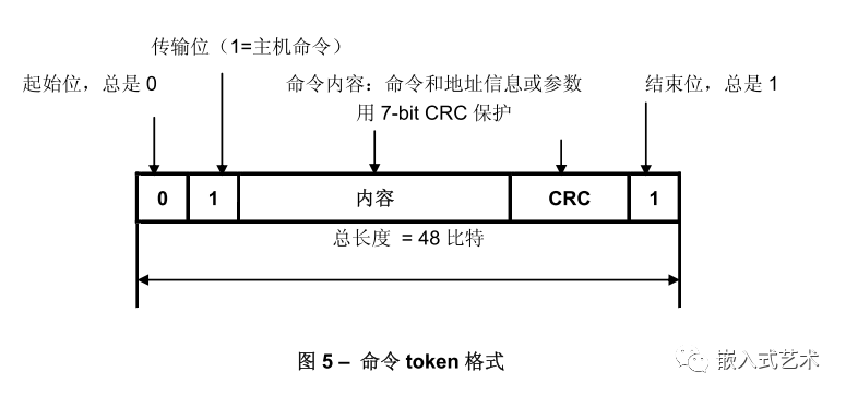
Each Token consists of a start bit (‘0’) at the front and ends with a stop bit (‘1’). The total length is 48 bits. Each Token is protected by CRC, allowing for error detection and repeatability.
Command formats can be divided into 4 modes:
① No Response Broadcast Command (bc)
② Response Broadcast Command (bcr)
③ Point-to-Point Addressing Command (ac), no DAT data
④ Addressing Data Transfer Command (adtc), with DAT data
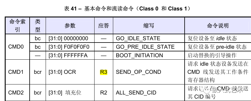
Command Index: This refers to the command numbers like CMDX, 0, 1, 2, 3, etc.
Command Parameters: Some commands require parameters, such as address information.
2.3 Response Format
All responses are sent through the CMD line, and the encoding length depends on the response type. The response Token types have 5 coding schemes: R1, R2, R3, R4, R5. The Token length is 48 or 136 bits.
① R1 (Normal Response Type)
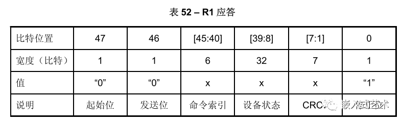
Encoding length 48bit, bits 45:40 indicate the response relative to the command index, bit 8:39 indicates the status information of the device to be sent.
② R2 (CID CSD Register)
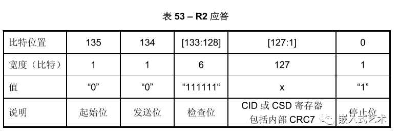
Encoding length 136bit, the content of the CID register is sent as a response to CMD2 and CMD10. The content of the CSD register is sent as a response to CMD9. Only bit 127:1 is sent for the CID and CSD registers.
③ R3 (OCR Register)
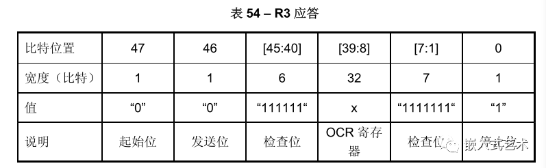
Encoding length 48bit, the OCR register is sent as a response to CMD1.
④ R4 (Fast I/O)
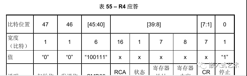
Encoding length 48bit, the parameter field contains the RCA of the addressed device, the address and content of the register to be read/write.
⑤ R5 (Interrupt Request)
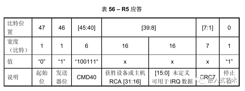
Encoding length 48bit, if the response is generated by the host, the parameter RCA should be 0.
3. Operating Modes
Communication between the host and device is initiated by the host, which sends commands to prompt responses from the device.
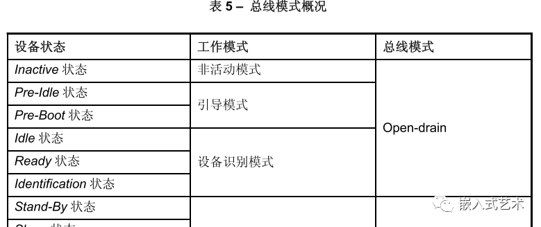
The EMMC operating mode also defines 5 types:
-
Boot Mode: Puts the device in boot state. -
Device Identification Mode: After boot mode ends, the device enters identification mode to accept the SET_RCAcommand to identify the device. -
Data Transfer Mode: After assigning RCA, the device enters data transfer mode to prepare for data communication. -
Interrupt Mode: Both host and device enter without data transmission, allowing only messages from the host or slave’s interrupt requests. -
Inactive Mode: The device enters inactive mode if the working voltage range and access mode are invalid.
Each mode has its own characteristics; we will mainly focus on the device identification process and the data transfer process.
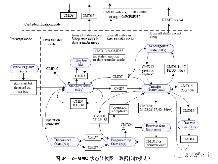
3.1 Device Identification Mode
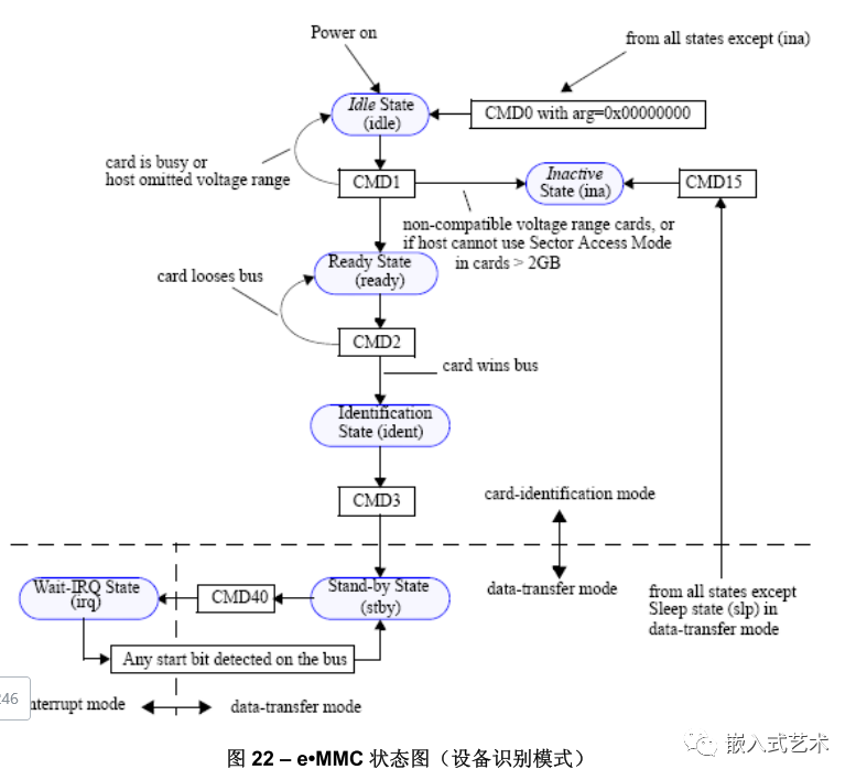
At first glance, the diagram may seem confusing without a detailed analysis of the protocol; it can be difficult to understand just by looking at it.
Overall, in device identification mode, the host must identify the card through the following steps:
-
Reset the Device
-
Verify Operating Voltage and Access Mode
-
Identify the Device and Assign Relative Device Address
RCA -
Put the Device into Data Transfer Mode
3.1.1 Reset
The EMMC Controller sends CMD0 with a parameter of 0x00000000 to put the device into Idle state.
To maintain backward compatibility, any parameter received that is not 0XFFFFFFFA or 0XF0F0F0F0 in any state except Inactive is treated as CMD0.
3.1.2 Verify Operating Voltage and Access Mode
The EMMC Controller sends CMD1 with a parameter of OCR Register, which contains 2bit of memory access mode.
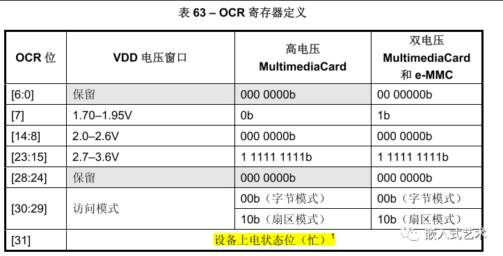
As shown, bit[30:29] indicates the access mode; the purpose of sending this data via CMD1 is to synchronize the addressing type to the memory.
The EMMC Device should also respond with a fixed mode of 0x00FF8080 or 0x40FF8080 (if the device is busy), 0x80FF8080 (if the capacity is less than or equal to 2GB), or 0xC0FF8080 (if the capacity is greater than 2GB).
Additionally, bit31 is used to indicate busy status; if it is 1, it means the EMMC Device is still in the reset process, and the host should repeatedly send CMD1 to ensure this busy bit is cleared.
3.1.3 Identify Device and Assign RCA
After checking with CMD1, devices that do not meet the requirements enter the Inactive state, while those that do enter the Ready state.
Then, the EMMC Controller sends CMD2, requesting the compliant device to send its Unique Device Identifier CID number. The CID number is unique for each card.
Devices that successfully send CID enter the Identification state.
Next, the EMMC Controller sends CMD3, assigning the device a relative device address RCA. Once the device receives RCA, it enters the Stand-by state, which is the Data Transfer State.
3.2 Data Transfer Process
After assigning RCA, when the slave device receives RCA, it immediately enters stand-by state, and both CMD and DAT lines change to push-pull mode.
3.2.1 Get CSD Register Information
CMD9: The host sends this command to obtain the device-specific register CSD data, such as block length, storage capacity, maximum clock rate, etc.
3.2.2 Get CID Register Information
CMD10: The host sends this command to obtain the device-specific register CID data, retrieving the device identification number.
3.2.3 Switch to Transfer State
CMD7: The host sends this command to select the device and switch it to the data sending state.
3.2.4 View EXT_CSD Extended Register
CMD8: The host sends this command, and the device sends its EXT_CSD register data as a 512-byte data block.
3.2.5 Modify EXT_CSD Extended Register Values
CMD6: The host sends this command to switch working modes or modify the EXT_CSD register.
The parameter settings for CMD6 are very important!
[31:26]: As the manual states, set directly to 0.
[25:24]: Access mode selection; what access modes are available?
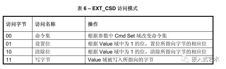
If the SWITCH command is used to change the command set ([25:24] is 00), the Index and Value fields are ignored ([23:16], [15:8] ignored), and the EXT_CSD will not be written.
If the SWITCH command is used to write to the EXT_CSD register, the Cmd Set field is ignored [2:0] ignored, and the command set remains unchanged.
[23:16]: Index, referring to the byte index in the EXT_CSD register that needs to be modified.
[15:8]: Value to be written.
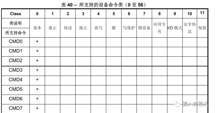
[2:0]: Command set selection; there are several categories of command sets that can be referenced in the relevant manual.
For example:
If we want to operate the bus width, how do we modify it?
For the CMD6 command, send args=03B70200 to modify it.
03: Indicates that the access mode is write byte.
B7: Converted to decimal 183, corresponding to the byte of the EXT_CSD bus width mode.

02: Set the value of this byte to 02, which means 8-bit data bus.
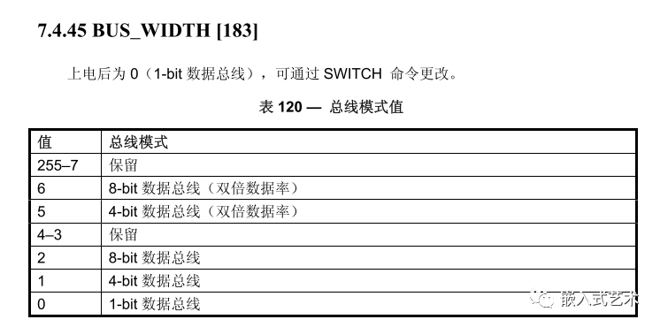
00: In write byte access mode, this bit is invalid.
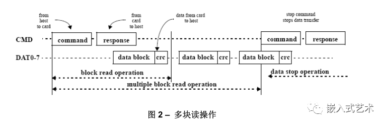
3.2.6 Read Data
-
Single Block Read
CMD17: Directly sends a read command, with the parameter as the data address information, reading only one block.
-
Multiple Block Read
CMD18: Directly sends a read command, with the parameter as the data address information, and continues reading.
CMD12: Stop command, halting transmission.
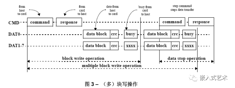
3.2.7 Write Data
Ensure the device is in sending state, i.e., the host sends
CMD7command.
-
Single Block Write
CMD24: Directly sends a write command, with the parameter as the data address information, writing only one block.
-
Multiple Block Write
There are two modes for multiple block writing:
① One is: Set the number of data blocks to be transmitted, which will automatically stop after reaching the count.
CMD16: Set the block length to be transmitted.
CMD25: Start sending data blocks specified by CMD16 until the set data blocks are completed.
② The other is: Continuously transmit data until a stop data command is received.
CMD25: Start sending data blocks, continuously waiting for data to be fully sent.
CMD12: Stop command, halting transmission.
Due to recent changes in WeChat public platform push rules, many readers have reported not seeing updated articles in time. According to the latest rules, it is recommended to frequently click on “Recommend Reading, Share, Collect”, etc., to become a regular reader.
Recommended Reading:
-
430 billion in hand! The EU unanimously passed the amendment to the chip bill, and a tripartite balance has been established.
-
Abandoning Samsung in South Korea! Tesla’s (Full) autonomous driving chip huge order settled at TSMC.
-
Directly abandoning the market due to contract renewal conflicts? You’re still too young~
-
Discontent with the largest wafer factory being acquired by a Chinese company, this operation has angered the UK.
-
Officials reveal: South Korea will join Chip 4! But will not impose export restrictions?
Please click on 【View】 to give the editor a thumbs up
