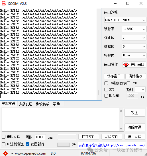
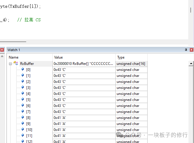
Friends, recently I needed to use SPI communication, so I used two boards, the STM32F03C8T6 and the ESP32, to implement SPI communication between them. Here, the STM32 acts as the SPI master, using the STM32 standard library functions. The ESP32 acts as the SPI slave, using the ESP-IDF spi_slave driver.P.S. I searched online for a long time and couldn’t find a program for the ESP32 as an SPI slave that could directly communicate with the STM32, so I explored and came up with a working program. Without further ado, let’s look at the results. The above shows the data received by the slave ESP32, and below is the data received by the master STM32.
Master and Slave Programs
Slave ESP32 Program:
extern "C" {
#include "driver/spi_slave.h"
#include "driver/gpio.h"
}
#include <Arduino.h>

#define PIN_NUM_MISO 19  //A6
#define PIN_NUM_MOSI 23  //A7
#define PIN_NUM_CLK  18  //A5
#define PIN_NUM_CS   5  //A4

uint8_t rxData[16] = {0};
uint8_t txData[8] = {0};

void setup() {
  Serial.begin(115200);

spi_bus_config_t buscfg = {
      .mosi_io_num = PIN_NUM_MOSI,
      .miso_io_num = PIN_NUM_MISO,
      .sclk_io_num = PIN_NUM_CLK,
      .quadwp_io_num = -1,
      .quadhd_io_num = -1,
  };

spi_slave_interface_config_t slvcfg = {
      .spics_io_num = PIN_NUM_CS,
      .queue_size = 3,
      .mode = 0,  // SPI mode 0
  };

for (int i = 0; i < 8; i++)    // Initialize the sending array
  {
      txData[i] = 67; // Corresponds to ASCII code C, hexadecimal 0x43
  }
// Initialize SPI slave interface
  ESP_ERROR_CHECK(spi_slave_initialize(HSPI_HOST, &buscfg, &slvcfg, 0));
}

void loop() {
spi_slave_transaction_t t;
memset(&t, 0, sizeof(t));
//memset(rxData, 0, sizeof(rxData));   // Clear previous data

t.length = 32*8;
t.tx_buffer = txData;
t.rx_buffer = rxData;
esp_err_t ret = spi_slave_transmit(HSPI_HOST, &t, portMAX_DELAY);

if (ret == ESP_OK) {
    Serial.printf("Hello ESP32!,%s\r\n", rxData);
  }
}
Master STM32 Program:
#include "stm32f10x.h"
#include <string.h>

uint8_t TxBuffer[16]= {0};
uint8_t RxBuffer[16]= {0};

void GPIO_Config(void) {
    GPIO_InitTypeDef GPIO_InitStructure;

    // Enable GPIO clocks
    RCC_APB2PeriphClockCmd(RCC_APB2Periph_GPIOA | RCC_APB2Periph_GPIOC, ENABLE);

    // SPI1 SCK, MOSI
 GPIO_InitStructure.GPIO_Pin = GPIO_Pin_5 | GPIO_Pin_7;
    GPIO_InitStructure.GPIO_Mode = GPIO_Mode_AF_PP;//GPIO_Mode_AF_PP;
    GPIO_InitStructure.GPIO_Speed = GPIO_Speed_50MHz;
    GPIO_Init(GPIOA, &GPIO_InitStructure);

// Configure PA4 as a normal push-pull output CS
 GPIO_InitStructure.GPIO_Pin = GPIO_Pin_4;
 GPIO_InitStructure.GPIO_Mode = GPIO_Mode_Out_PP; // Push-pull output
 GPIO_Init(GPIOA, &GPIO_InitStructure);

    // SPI1 MISO (Input floating)
    GPIO_InitStructure.GPIO_Pin = GPIO_Pin_6;
    GPIO_InitStructure.GPIO_Mode = GPIO_Mode_AF_PP;
    GPIO_Init(GPIOA, &GPIO_InitStructure);

    // PC13 for LED
    GPIO_InitStructure.GPIO_Pin = GPIO_Pin_13;
    GPIO_InitStructure.GPIO_Mode = GPIO_Mode_Out_PP;
    GPIO_InitStructure.GPIO_Speed = GPIO_Speed_2MHz;
    GPIO_Init(GPIOC, &GPIO_InitStructure);
}

void SPI1_Config(void) {
    SPI_InitTypeDef SPI_InitStructure;

    RCC_APB2PeriphClockCmd(RCC_APB2Periph_SPI1, ENABLE);

    SPI_InitStructure.SPI_Direction = SPI_Direction_2Lines_FullDuplex;
    SPI_InitStructure.SPI_Mode = SPI_Mode_Master;
    SPI_InitStructure.SPI_DataSize = SPI_DataSize_8b;
    SPI_InitStructure.SPI_CPOL = SPI_CPOL_Low;   // Mode 0
    SPI_InitStructure.SPI_CPHA = SPI_CPHA_1Edge;
    SPI_InitStructure.SPI_NSS = SPI_NSS_Soft;
    SPI_InitStructure.SPI_BaudRatePrescaler = SPI_BaudRatePrescaler_16;
    SPI_InitStructure.SPI_FirstBit = SPI_FirstBit_MSB;
    SPI_InitStructure.SPI_CRCPolynomial = 7;
    SPI_Init(SPI1, &SPI_InitStructure);

    SPI_Cmd(SPI1, ENABLE);
}

uint8_t SPI1_SendByte(uint8_t byte) {
    // Wait for the transmit buffer to be empty
    while (SPI_I2S_GetFlagStatus(SPI1, SPI_I2S_FLAG_TXE) == RESET);
    SPI_I2S_SendData(SPI1, byte);

    // Wait for reception to complete
    while (SPI_I2S_GetFlagStatus(SPI1, SPI_I2S_FLAG_RXNE) == RESET);
    return (uint8_t)SPI_I2S_ReceiveData(SPI1);
}

int main(void) {
    SystemInit();
    GPIO_Config();
    SPI1_Config();

for (uint8_t i = 0; i < 16; i++)    // Initialize the sending array
    {
        TxBuffer[i] = 65;  // Corresponds to ASCII code A, so the ESP32 displays character A on the serial monitor
    }


    while (1) {
        GPIO_SetBits(GPIOC, GPIO_Pin_13);
        for (volatile int i = 0; i < 1000000; i++);

        GPIO_ResetBits(GPIOC, GPIO_Pin_13);
        for (volatile int i = 0; i < 1000000; i++);

  GPIO_ResetBits(GPIOA, GPIO_Pin_4); // Pull CS low
        // Send string to ESP32
        for (int i = 0; i < 16; i++) {
            RxBuffer[i] = SPI1_SendByte(TxBuffer[i]);
        }
  GPIO_SetBits(GPIOA, GPIO_Pin_4);   // Pull CS high
    }
}
Notes:
1. In the ESP32 program, t.length must be greater than the size of the data sent by the STM32; if it is smaller, there will be transmission errors. Note that t.length is in bits. (This point is crucial)
2. When connecting the two boards, ensure that MOSI is connected to MOSI and MISO is connected to MISO, do not cross-connect.
3. As the STM32 master, the position of pulling the chip select line CS low when sending data is very important. Pay attention to the position in my program where CS is pulled low, as this affects whether the ESP32 can receive all data correctly.
4. Remember to connect the grounds of the two boards.
5. Pay attention to the mode of several SPI pins on the STM32, as indicated in the program’s GPIO_InitStructure.GPIO_Mode.