UART, I2C, and SPI are common low-speed board-level communication protocols. Currently, mainstream SoCs are equipped with controllers for these communication protocols, and various sensors, touch controllers, fingerprint modules, Bluetooth modules, and Wi-Fi modules are compatible with one or more of these communication methods.
Below, we will discuss each protocol:UART UART generally consists of three lines: TXD, RXD, and GND, and is an asynchronous transmission protocol. Both the master and slave can freely send data, but since the UART bus does not have a clock line, the corresponding baud rate must be agreed upon in advance. This is a very simple transmission protocol. 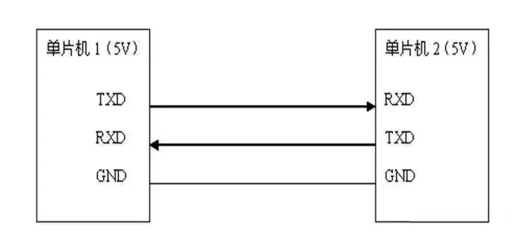 I2C
I2C
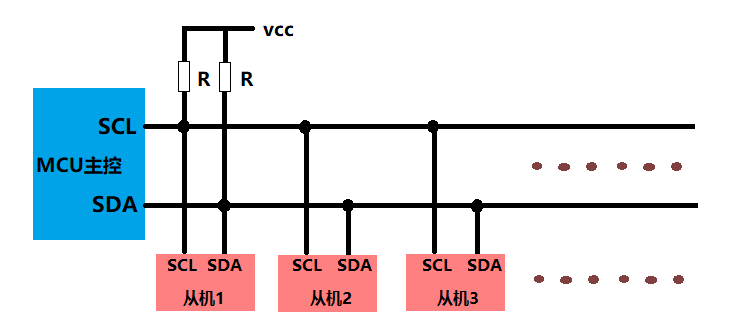
I2C uses two lines, SDA (data) and SCL (clock), and is also a synchronous transmission protocol. After the master sends a start signal, it first sends a 7-bit address and a 1-bit read/write bit. Each slave has its own I2C address, and when it detects that the command is directed to itself, it pulls the SDA line low (i.e., responds with an ACK signal), after which the master sends or receives data to complete the transmission. After the transmission is complete, the master sends a stop bit to finish the transmission.
Recommended reading:Understanding the IIC Communication Protocol, this article is sufficient.
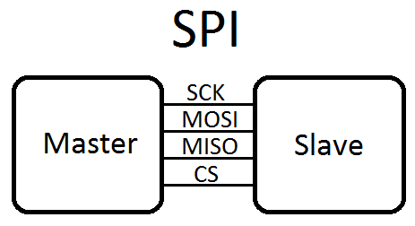
SPI SPI consists of four lines: CS (chip select), MOSI (master out slave in), MISO (slave out master in), and CLK (clock), and is a synchronous transmission protocol. The master sends out the CLK signal, data from the master to the slave is transmitted on the MOSI line, and data from the slave to the master is transmitted on the MISO line. Before starting the transmission, the corresponding slave’s CS pin must be pulled low (generally this way, although some chips have active high CS). After the transmission is complete, the CS pin is pulled high, putting the slave’s SPI Slave module into sleep mode.
Usage Scenarios First, both I2C and SPI are synchronous protocols and have clock signals, allowing multiple slave devices to be connected on a single bus. However, I2C distinguishes slave devices by address, while SPI distinguishes them by chip select lines. Therefore, for each additional slave device on the SPI bus, an additional line is required for the chip select, whereas I2C does not require this as long as the addresses do not conflict, allowing for arbitrary device connections. However, the I2C bus speed is generally slower than SPI. Typical I2C speeds are 100kbps, 400kbps, and 1Mbps, while SPI speeds can reach several Mbps or even 10+ Mbps. Therefore, depending on the application, I2C is suitable for low-speed scenarios, while SPI is generally chosen for higher speeds. Additionally, the I2C bus pins are open-drain outputs and must be connected to pull-up resistors, with the resistance value calculated based on the bus speed. For a common transmission rate of 400kbps, a pull-up resistor of 2.2K is typically used. UART, unlike SPI and I2C, is an asynchronous transmission protocol. Generally, its transmission speed is slower, with traditional speeds typically at 115200bps or lower. However, most modern UART controllers can support speeds up to 4Mbps or 8Mbps. Currently, UART is most commonly used as a debugging interface, as it is relatively simple, and CPU log outputs are generally sent through a UART port.