Table of Contents
1. Key Technical Features of RS-485
2. Application Scenarios
3. Standards
4. Advantages of Using Differential Signal Transmission
5. Similarities and Differences Between RS-422 and RS-485
5.1 Differences in Bus Architecture
5.2 Differences in Common Mode Voltage Range
5.3 Differences in Input Impedance of Receivers
5.4 RS-485 Transceivers with Enable Pins
6. Termination Resistors
6.1 Differential Transmission Lines
6.2 Reflections and Cable Length
6.3 Termination Resistor Placement
6.4 Termination Methods
6.5 Branch Line Lengths
6.6 Data Rate and Cable Length
7. EMC and Protection
7.1 Differential Input Threshold Voltage of Receivers
7.2 Enabling Fail-Safe
7.3 Isolation
7.4 Transient Overvoltage Stress Protection
7.5 EMC Circuit Solutions for RS-485 Interfaces
1. Key Technical Features of RS-485
Long-distance links—up to 4000 feet, 1 foot = 0.3048 meters, 1200m;
Bidirectional communication on a pair of twisted cables;
Differential transmission increases noise immunity and reduces noise radiation;
Multiple drivers and receivers can be connected to the same bus;
A wide common mode range allows for ground potential differences between drivers and receivers;
TIA/EIA-485-A allows for data rates up to 10 Mbps, but devices compliant with the TIA/EIA-485-A specifications are not required to operate across the entire range and are not limited to 10 Mbps;
2. Application Scenarios
Process control networks, industrial automation, remote terminals, building automation (e.g., HVAC), security systems, motor control, and motion control, etc.
3. Standards
TIA/EIA-485-A: The most widely used transmission line standard in the telecommunications industry, describing the physical layer of the RS-485 interface, typically used in conjunction with higher-level protocols such as Profibus, Interbus, Modbus, BACnet, etc., enabling stable data transmission over relatively long distances.
TIA/EIA-422-B: The physical layer of RS-422 is specified in TIA/EIA-422-B. The TIA/EIA-485-A standard is similar to the TIA/EIA-422-B standard, and the driver and receiver values specified in the TIA/EIA-485-A standard comply with both standards.
4. Advantages of Using Differential Signal Transmission
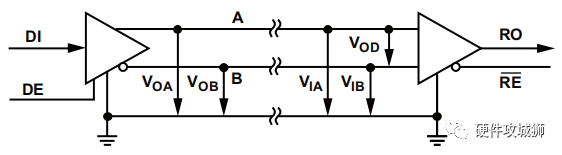
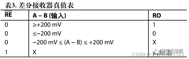
If VIA – VIB > 200mV, the receiver outputs a logic high (RO = 1). If VIA – VIB < -200mV, i.e., VIB – VIA > 200mV, the receiver outputs a logic low (RO = 0).
The receiving end uses the difference between signals A and B (200mV) as the basis for level judgment, improving the capability against common-mode interference.
The output levels of signals A and B can be higher or lower than those of the receiving end, so the voltage drop on the transmission cable does not affect level judgment (but if the cable is too long, the noise margin of the signal will decrease).
The current direction on the A and B signal lines is always opposite, creating magnetic fields that cancel each other out, reducing EMI.
Common mode voltage (VCM) is defined as: VCM = (VIA + VIB)/2
5. Similarities and Differences Between RS-422 and RS-485
Similarities: Allow data rates up to 10 Mbps, with a maximum line length of 4000 feet.
Differences:
5.1 Differences in Bus Architecture
RS-422 is a simplex multi-branch standard, allowing only one driver and up to 10 receivers to be connected to the same bus, as shown in the figure below.
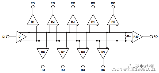 Figure: Typical RS-422 Interface Circuit
RS-485 is specified as a multipoint standard, allowing up to 32 transceivers to be connected to the same bus, as shown in the figure below.
Half-duplex: RS-485 transceivers must have driver/receiver enable pins, enabling only one driver to send data at a time.
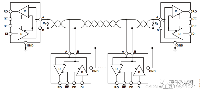 Figure: Half-Duplex RS-485 Bus Configuration
Full-duplex: RS-485 allows bidirectional simultaneous communication between master and slave nodes.
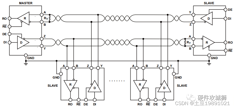 Figure: Full-Duplex RS-485 Bus Configuration
5.2 Differences in Common Mode Voltage Range
RS-422 receivers can withstand a common mode voltage (VCM) of ±7 V, while RS-485 extends the common mode voltage range from -7 V to +12 V.
5.3 Differences in Input Impedance of Receivers
RS-422 receiver input impedance must be greater than or equal to 4 kΩ.
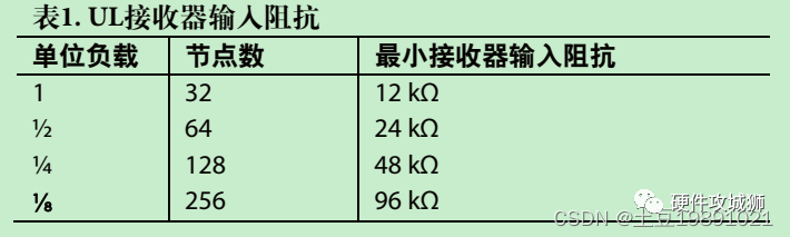
RS-485 receivers are rated with an input impedance of greater than or equal to 12 kΩ. This impedance is defined as having one unit load (UL). The maximum load capacity specified in the RS-485 standard is 32 UL. Some RS-485 receivers are rated at ¼ UL or ⅛ UL.
5.4 RS-485 Transceivers with Enable Pins
The DE pin set to low (DE = 0) can place the driver in a high-impedance state, effectively disconnecting the driver from the bus. This allows the RS-485 bus to support multi-driver networking. Similarly, the RE pin is used to enable/disable the receiver (high-impedance state), reducing driver power consumption.
6. Termination Resistors
6.1 Differential Transmission Lines
There are two wires in a transmission line, one carries current from the driver to the receiver, and the other provides a return path to the driver. To achieve reliable RS-485 and RS-422 communication, reflections in the transmission line must be minimized, which requires proper cable termination.
6.2 Reflections and Cable Length
Reflections occur immediately during and after signal transitions. On longer lines, reflections are more likely to persist long enough to cause the receiver to misinterpret logic levels. On shorter lines, the duration of reflections is much shorter, thus having no impact on the received logic levels. This explains why in practical 485 networking tests, shorter cables do not require termination resistors, while longer cables do.
6.3 Termination Resistor Placement
In RS-422 applications, there is only one driver on the bus, and if termination is to be used, it must be placed at the far end of the cable of one receiver. According to the requirements of RS-485 applications, termination should be at the master node and the farthest slave node from the master.
6.4 Termination Methods
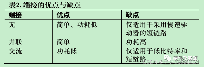
No Termination
For longer cables, propagation time is also longer, and for shorter cables, propagation time is shorter. If the signal rise time is more than four times the cable propagation delay time, the cable should not be treated as a transmission line.
Parallel Termination
Regardless of how many nodes are connected in the network, there should not be more than two termination resistors. The termination resistor value should equal the characteristic impedance of the cable. In half-duplex configurations, both ends of the cable must be terminated. In full-duplex configurations, only the master receiver and the farthest slave receiver need to be terminated.
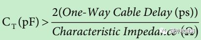
AC Termination
AC termination is used to reduce idle link power consumption and lower ringing voltage. However, the downside is that it reduces cable length and decreases bit rate. The capacitance CT is selected using the following formula:
6.5 Branch Line Lengths
Branch line lengths should be much shorter than one-quarter wavelength at the frequency equal to the inverse of the bit period.
6.6 Data Rate and Cable Length
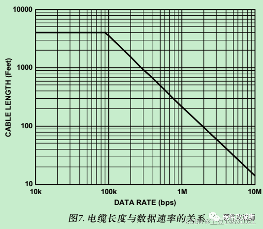
When using high data rates, only shorter cables should be used. For lower data rates, longer cables can be used. For low data rate applications, voltage drops across the DC resistance of the cable reduce noise margin, limiting cable length. For high data rates, AC effects of the cable limit signal quality and restrict cable length to shorter distances. For RS-422, the range of data rate/cable length varies from 90 kbps/4000 feet to 10 Mbps/15 feet.
The following is a more conservative curve of cable length versus data rate.
7. EMC and Protection
7.1 Differential Input Threshold Voltage of Receivers
7.2 Enabling Fail-Safe
During idle conditions on the bus, no devices drive the bus. The output of the receiver is in an undefined state. This can lead to random data being received on the UART, resulting in invalid start bits, false interrupts, and frame errors. To resolve this issue, pull-up and pull-down resistors can be placed simultaneously at one position on the bus. As shown in the figure below:
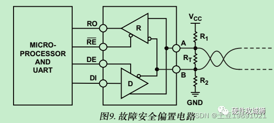
The calculations for R1 and R2 are as follows:
7.3 Isolation
In RS-485 applications, longer links are typically used, which can cause slight differences in ground potential among different nodes on the bus, resulting in ground currents. When non-isolated devices powered by DC power supplies are networked, ground loops can easily form between link ground and power ground, introducing ground noise. Isolation can effectively block the transfer of common-mode noise between nodes. Isolation must be applied to both signal lines and power supply.
7.4 Transient Overvoltage Stress Protection
Lightning strikes, power fluctuations, inductive switching, and electrostatic discharges can cause significant transient voltages that damage RS-485 transceivers. Therefore, ESD protection, EFT protection, and surge protection specifications are applicable to RS-485 applications.
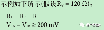
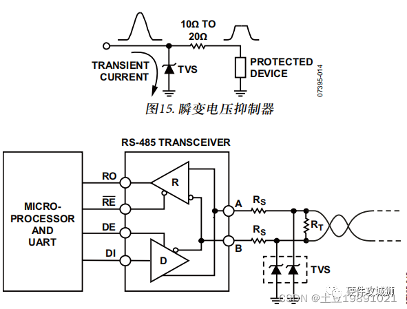
In RS-485 applications, the function of TVS is to clamp the voltage on the bus to the common mode voltage range of the RS-485 transceiver (-7 V to +12 V). A resistor RS (10 Ω to 20 Ω) can be added between the protected device and the TVS to enhance protection. As shown in the figure below:
7.5 EMC Circuit Solutions for RS-485 Interfaces
Common solutions include the following three types
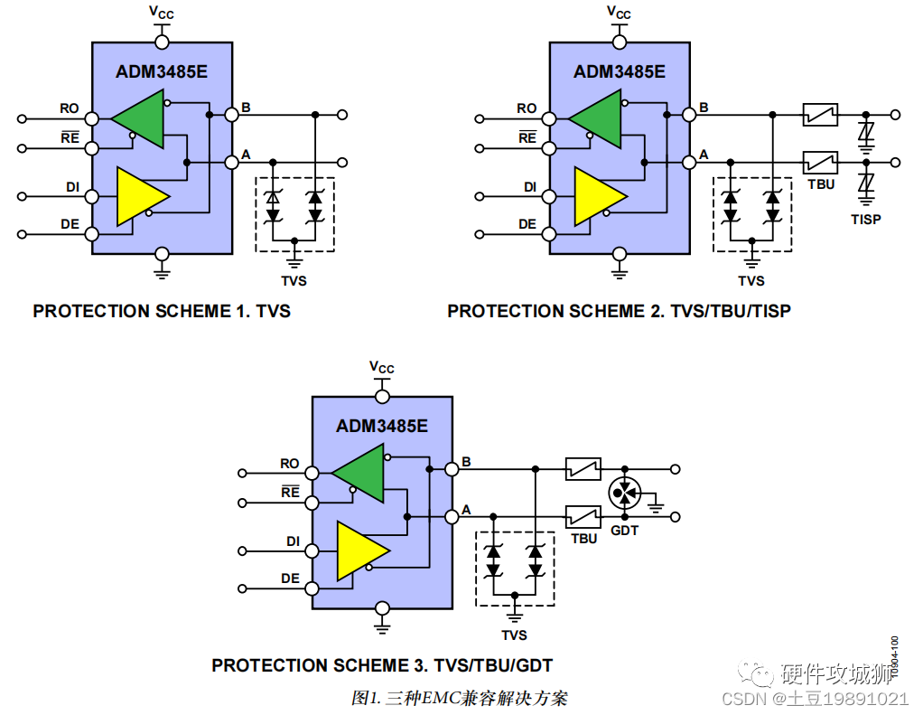
Transient interferences that RS-485 interfaces need to address mainly include: Electrostatic Discharge (ESD), Electrical Fast Transient (EFT), and Surge.
When designing transient protection circuits, the following points should be considered:
-
Must prevent or limit damage caused by transients, allowing the system to recover normal operation with minimal performance impact.
-
The protection scheme should be robust enough to handle various types of transients that the system may encounter in electromagnetic fields.
-
Transient duration is an important factor. For longer transients, thermal effects can cause certain protection schemes to fail.
-
Under normal operating conditions, the protection circuit should not interfere with system operation.
-
If the protection circuit fails due to over-stress, it should fail in a manner that protects the system.
-
There are two main types of protection schemes. Overcurrent protection is used to limit peak current, while overvoltage protection is used to limit peak voltage.
Typical two-stage protection, with the main protection handling most transient energy, and the secondary protection handling any transient voltage (residual voltage) and current allowed through by the main protection.
— End —
Recommended Reading