Zhang Weifeng1, Zhang Yanhui2, Luo Huan1
(1. Shenzhen Information Vocational Technology College, Guangdong Shenzhen 518172; 2. ZTE Corporation, Guangdong Shenzhen 518057)
Abstract: This paper proposes an AC detection circuit based on integrated operational amplifiers. The circuit consists of a voltage attenuation circuit, differential operational amplification and synthesis circuits, voltage zero-crossing detection, and frequency detection circuits. Through theoretical derivation, the calculation formulas for key parameters of the circuit are provided, and the circuit is simulated using Multisim software, with results consistent with theoretical calculations. Based on the simulation design parameters, an experimental circuit was built. The experimental results show that the actual detected voltage is 3.4 V, the zero-crossing detection signal is a 5 V square wave, and the frequency is 100 Hz, which is consistent with theoretical calculations and simulation results, verifying the feasibility of the designed circuit. The circuit is simple, reliable, and easy to implement, providing a new attempt for AC detection in various power supply and instrument systems.
Keywords: AC detection; zero-crossing detection; integrated operational amplifier; differential operational amplifier circuit
Classification Number: TM911.23 Document Identification Code: A DOI: 10.19358/j.issn.1674-7720.2017.05.011
Citation Format: Zhang Weifeng, Zhang Yanhui, Luo Huan. A Simple AC Voltage Detection Circuit [J]. Microcomputer and Applications, 2017, 36(5): 32-34.
0 Introduction
Fund Project: Guangdong Natural Science Foundation Doctoral Startup Project (S2012040007242); Shenzhen Science and Technology Project (JCYJ20160527101807403, JCYJ20140418100633638); Shenzhen Information Vocational Technology College Teaching Research Project (2016jgyb03). Currently, fields such as uninterruptible power supplies, emergency power supplies, high-frequency rectifiers, inverters, frequency converters, solar power generation, and wind power generation all require AC signal detection to obtain parameters such as voltage magnitude, frequency, and zero-crossing detection, thereby enabling precise control of the power supply [1-4]. In existing methods [5], the voltage is typically reduced through a transformer, then rectified and divided, and finally the voltage signal is collected by a microcontroller to obtain voltage detection data. Additionally, zero-crossing detection data is obtained through a zero-crossing detection circuit. However, this method requires implementing two circuits for voltage detection and zero-crossing detection, and requires components such as transformers, making the design complex and costly.
Based on this, this paper proposes an AC voltage detection circuit based on integrated operational amplifiers, which achieves simultaneous detection of AC signal voltage, voltage frequency, and zero-crossing parameters using simple discrete components and commonly used integrated operational amplifier devices, at a low cost, with simplicity, reliability, and ease of implementation.
1 Circuit Composition and Principle
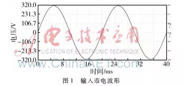
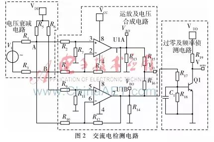
AC voltage detection includes voltage magnitude, frequency, and zero-crossing detection. The detected signals must be processed by a processor for precise control of the power supply system. Taking the mains power as an example, the effective value is 220 V, and the peak value is about 310 V, as shown in Figure 1. However, actual microcontroller control chips are low-voltage devices, so the detection circuit should include voltage attenuation circuits, operational amplification and synthesis circuits, and zero-crossing and frequency detection circuits, as shown in Figure 2.
1.1 Circuit Principle Analysis
AC detection is realized through a low-power control chip; the 220 V AC must be attenuated to a low voltage signal before being amplified and synthesized by the integrated operational amplifier circuit to be reliably received by microcontrollers and other control chips, allowing for reliable control of the entire system.
As shown in Figure 2, the voltage attenuation circuit consists of resistors R1, R3, R5, R6, and a DC bias voltage source. The mains voltage V1 is divided by four resistors, obtaining a millivolt-level weak voltage signal at nodes A and B. This weak signal serves as the input signal for the integrated operational amplifier, which is then proportionally amplified. To reduce the number of power supplies in practical applications, the integrated operational amplifier uses a single power supply, meaning that one operational amplifier circuit can only output the positive voltage of the AC signal. To fully restore the output AC signal, another integrated operational amplifier is required, with the input signal of the operational amplifier reversed, allowing the negative half-cycle voltage of the AC signal to be converted to a positive voltage output. The voltage signals VAO and VBO output from the two operational amplifier circuits are connected through two resistors to synthesize the AC voltage signal, with the output signal VO, which can be directly connected to microcontrollers or DSPs for subsequent computation and control processing. Either output signal from the two operational amplifiers can serve as the input for the zero-crossing and frequency detection circuits; in this paper, the negative voltage output is used as the input for the zero-crossing and frequency detection circuits. In the positive half-cycle of the AC voltage, the output from the operational amplifier is zero volts, and the switching transistor Q1 does not conduct, resulting in a high-level output for Vzero. When the positive voltage of the AC signal drops to zero, the negative voltage begins to increase, and the output voltage of the operational amplifier starts to increase, triggering the switching transistor Q1 to conduct, resulting in a low-level output for Vzero. As the AC voltage continues to alternate, Vzero becomes a pulse signal of high and low levels; the edges of the high and low levels indicate the zero-crossing points, and the period of the pulse signal corresponds to the period of the AC signal, allowing the microcontroller or DSP to capture the Vzero signal. After computation, the zero-crossing points and frequency parameters of the AC signal can be obtained.
1.2 Circuit Parameter Calculation
In practical applications, the voltages VAB at nodes A and B, the operational amplifier output voltages VAO and VBO, the synthesized voltage VO, and the zero-crossing detection signal Vzero are key parameters; therefore, the circuit must undergo equivalent analysis to calculate reasonable parameter values to ensure reliable operation of the detection circuit.
The voltage attenuation circuit is equivalent to the superposition of two voltage sources acting separately, allowing us to use the superposition theorem to obtain:

Where V1 is the detected AC voltage; in practical applications, we generally take R5=R6, R1=R3, thus:

In Figure 2, both integrated operational amplifier circuits are differential operational amplifier circuits; based on the characteristics of differential operational amplifier circuits, we have:
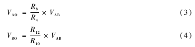
The synthesized voltage VO can be considered as the voltage superposition of VAO and VBO acting separately on the series circuit of R15 and R16; using the superposition theorem, we obtain:

In practical applications, taking R15=R16, we have:

2 Simulation and Experiment
In Multisim software, a simulation model was established based on the circuit shown in Figure 2 for mains detection. In practical applications, the detection of mains power is centered around 220 V, with positive and negative fluctuations of 20%. To ensure that the detected parameter values can be well captured by microcontrollers or DSPs, the range of the synthesized detection voltage is generally required to be within 5 V. Therefore, based on the above principle analysis and parameter calculations, the key parameters of the circuit model are selected as shown in Table 1.
Based on the parameters in Table 1, the circuit in Figure 2 was simulated using Multisim software.

Figure 3 shows the voltage waveform of the mains and the waveform of the attenuated signal. From the figure, it can be seen that the mains voltage of 220 V has a peak voltage of about 310 V, and the peak voltage of the attenuated signal is about 200 mV. Substituting the parameter values from Table 1 into formula (2), the peak value of the attenuated signal is calculated to be 200 mV, and the simulation result is consistent with the theoretical calculation.
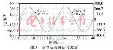
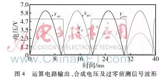
Figure 4 shows the output waveform of the differential operational circuit, the synthesized voltage waveform, and the zero-crossing voltage detection waveform. From the figure, it can be seen that during the positive half-cycle of the mains, the output VAO of the differential operational amplifier circuit is a positive half-wave with a peak value of 6.7 V, while VBO outputs zero; during the negative half-cycle of the mains, the output VBO of the differential operational amplifier circuit is a positive half-wave with a peak value of 6.7 V, while VAO outputs zero; the synthesized voltage waveform is a positive half-wave, with both half-cycles being positive, and the peak value is 3.35 V; the zero-crossing detection signal Vzero is triggered at the zero-crossing of the sine AC voltage, with a frequency of twice that of the sine AC voltage and an amplitude of 5 V. Substituting the parameters from Table 1 into formulas (3), (4), and (6), the peak values of VAO and VBO are calculated to be 6.76 V, and the peak value of VO is 3.38 V. Thus, it can be seen that the simulation is consistent with the theoretical calculation.
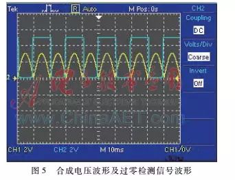
To verify the actual working effect of the circuit, an experimental circuit was built based on the parameters in Table 1. The experimental waveforms are shown in Figure 5. In the figure, channel 1 represents the synthesized voltage waveform, and channel 2 represents the zero-crossing detection signal. From the figure, it can be seen that the synthesized signal is a positive half-wave waveform with an amplitude of about 3.4 V; the zero-crossing detection signal is a square wave of about 5 V, which triggers the circuit level transition at the zero-crossing of the AC voltage during both the positive and negative half-cycles, with a frequency of 100 Hz. The experimental results are consistent with the simulation and theoretical calculations.
The synthesized voltage and zero-crossing detection signals will ultimately be connected to the A/D port of the microcontroller or DSP control chip, and then processed through control algorithms for computation, allowing for precise control of the power supply system. Simulation and experimental results show that both the synthesized voltage and zero-crossing detection signals are positive and within the range of 5 V, suitable for A/D sampling by control chips, facilitating the design of the control system.
3 Conclusion
This paper presents an AC detection circuit based on integrated operational amplifier devices. The circuit consists of simple discrete resistors, integrated operational amplifiers, transistors, and other components, making it low-cost, simple, reliable, and easy to implement. The experimental results are consistent with theoretical analysis and simulation results, verifying the feasibility of the designed circuit and providing a simple and feasible solution for AC detection in fields such as uninterruptible power supplies, emergency power supplies, high-frequency rectifiers, inverters, frequency converters, solar power generation, wind power generation, and electrical measurement instruments.
References
[1] Zhu Longji, Liu Hui. Research on Phase-Locked and Phase-Switching Technology of Three-Phase UPS Power Supply [J]. Journal of Anhui University of Science and Technology, 2007, 27(4): 29-32.
[2] Xue Jiaxiang, Shen Dong, Zhang Sizhang, et al. Research on Electrical Parameter Detection System of Single-Phase Photovoltaic Grid-Connected Inverter [J]. Renewable Energy, 2012, 30(11): 24-29.
[3] Yao Zhengwu. Accurate Zero-Crossing Detection Technology for Thyristor Conversion Equipment [J]. Electronic Devices, 2014, 37(6): 1256-1260.
[4] Yao Weipeng. Design of a New Type of AC Detection Circuit [J]. Digital Technology and Applications, 2015(10): 71.
[5] Ren Hongbin, Leng Jianwei. AC Voltage Detection Based on STM32 [J]. Electronic Design Engineering, 2016, 24(13): 133-135.