-
Introduction to eMMC
-
Host Interface
-
Flash Controller
-
Flash Memory
-
eMMC Partition Management
-
Boot Area Partitions
-
Examples of eMMC Partition Applications
-
eMMC Bus Protocol
-
eMMC Bus Interface
-
eMMC Bus Model
Introduction to eMMC
eMMC stands for embedded MultiMediaCard. MultiMediaCard, or MMC, is a standard for flash memory cards that defines the architecture and interface for accessing Flash Memory. eMMC is an extension of MMC designed to meet higher standards for performance, cost, size, stability, and ease of use.
The overall architecture of eMMC is shown in the image below:
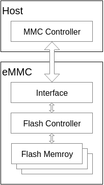
Internally, eMMC can be divided into three main parts: Flash Memory, Flash Controller, and Host Interface.
Host Interface
The connection between eMMC and the Host is illustrated in the figure below:
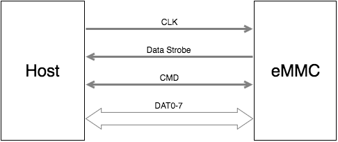
The purposes of the various signals are as follows:
- CLK: Clock signal for synchronization
- Data Strobe: This signal is a clock signal output from the Device, with the same frequency as the CLK signal, used to synchronize data output from the Device. This signal was introduced in eMMC 5.0.
- CMD: This signal is used to send commands from the Host and responses from the Device.
- DAT0-7: An 8-bit bus used for data transmission.
Communication between the Host and eMMC is initiated by the Host starting with a Command. The Device will respond differently based on the Command. For detailed communication protocol information, refer to the eMMC bus protocol section.
Flash Controller
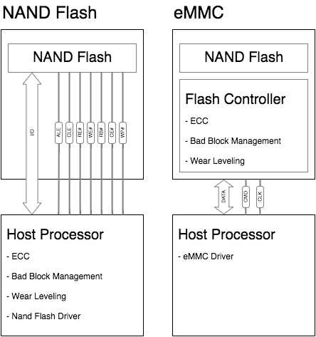
When NAND Flash is directly connected to the Host, the Host typically requires a NAND Flash Translation Layer (NFTL) or NAND Flash file system for bad block management, ECC, and other functions.
eMMC integrates a Flash Controller internally to handle wear leveling, bad block management, ECC checks, and other functions. Compared to directly connecting NAND Flash to the Host, eMMC abstracts the physical characteristics of NAND Flash, reducing the complexity of the Host software and allowing it to focus on higher-level tasks without special handling of NAND Flash. Additionally, eMMC employs technologies like Cache and Memory Array, significantly improving read and write performance compared to NAND Flash.
Flash Memory
Flash Memory is a type of non-volatile storage typically used in embedded systems to store the system, applications, and data, similar to hard drives in PC systems. Currently, most of the Flash Memory used in mobile devices like smartphones and tablets is NAND Flash.
eMMC internally divides Flash Memory into several main areas, as shown in the image below:
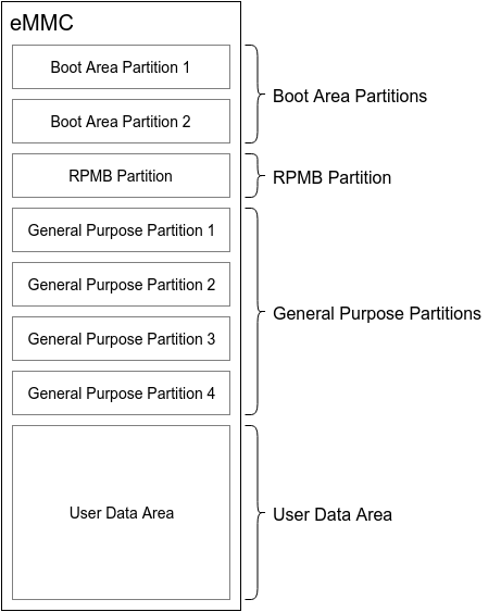
- BOOT Area Partition 1 & 2
This partition is primarily designed to support system booting from eMMC. The data in this partition can be read out through a simple protocol after powering on the eMMC. Most SOCs can be configured via GPIO or FUSE to load the contents of the eMMC BOOT partition into the SOC’s internal SRAM for execution after power-up.
- RPMB Partition
RPMB stands for Replay Protected Memory Block, which uses HMAC SHA-256 and a Write Counter to ensure that the data stored in RPMB cannot be tampered with illegally. In practical applications, the RPMB partition is typically used to store security-related data, such as fingerprint data and keys related to secure payments.
- General Purpose Partition 1~4
This area is mainly used for storing system or user data. General Purpose Partitions typically do not exist at the factory and must be actively configured to be created.
- User Data Area
This area is primarily used for storing system and user data. The User Data Area is often further partitioned; for example, in Android systems, it typically includes boot, system, userdata, and other partitions.
eMMC Partition Management
Boot Area Partitions
The Boot Area contains two Boot Area Partitions, primarily used to store the Bootloader, supporting SOC booting from eMMC.
1. Capacity Size
The sizes of the two Boot Area Partitions are identical, determined by the BOOT_SIZE_MULT field of the Extended CSD register, with the size calculated as follows:
Size = 128Kbytes x BOOT_SIZE_MULT
Generally, the size of the Boot Area Partition is 4 MB, meaning BOOT_SIZE_MULT is 32. Some chip manufacturers provide the ability to rewrite BOOT_SIZE_MULT to change the capacity of the Boot Area Partition. The maximum value for BOOT_SIZE_MULT is 255, meaning the maximum capacity of the Boot Area Partition can be 255 x 128 KB = 32640 KB = 31.875 MB.
2. Booting from the Boot Area
eMMC defines a Boot State. After Power-up, HW reset, or SW reset, if certain conditions are met, eMMC will enter this State. The conditions for entering the Boot State are as follows:
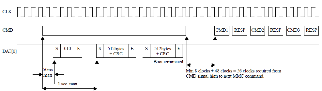
- Original Boot Operation
The CMD signal must remain low for at least 74 clock cycles to trigger the Original Boot Operation and enter the Boot State.
- Alternative Boot Operation
After 74 clock cycles, if the CMD signal is pulled low for the first time or the Host sends CMD1 before the Host sends COM0 with a parameter of 0xFFFFFFFA, it will trigger the Alternative Boot Operation and enter the Boot State.
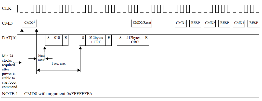
In the Boot State, if BOOT_ACK is configured, eMMC will first send an “010” ACK packet, followed by sending a maximum of 128Kbytes x BOOT_SIZE_MULT of Boot Data to the Host. During the transmission, the Host can interrupt eMMC’s data sending by pulling the CMD signal high (in Original Boot) or sending a Reset command (in Alternative Boot) to complete the Boot Data transmission.
Boot Data can be read from Boot Area Partition 1, Boot Area Partition 2, or User Data Area based on the settings of the PARTITION_CONFIG field’s Bit[5:3]:BOOT_PARTITION_ENABLE in the Extended CSD register.
3. RPMB Partition
The RPMB (Replay Protected Memory Block) Partition is a secure partition within eMMC. When writing data to RPMB, eMMC verifies the legality of the data, allowing only designated Hosts to write, while also providing a signature mechanism during data reading to ensure that the data read by the Host is from RPMB and not forged by an attacker.
In practical applications, RPMB is typically used to store data that requires protection against illegal tampering, such as public keys and serial numbers related to fingerprint payments on mobile phones. RPMB can authenticate write operations, but reading does not require authentication, allowing anyone to read the data; therefore, data stored in RPMB is usually encrypted before storage.
- 3.1 Capacity Size
The size of the RPMB Partition is determined by the BOOT_SIZE_MULT field of the Extended CSD register, with the size calculated as follows:
Size = 128Kbytes x BOOT_SIZE_MULT
Generally, the size of the RPMB Partition is 4 MB, meaning RPMB_SIZE_MULT is 32. Some chip manufacturers provide the ability to rewrite RPMB_SIZE_MULT to change the capacity of the RPMB Partition. The maximum value for RPMB_SIZE_MULT is 128, meaning the maximum capacity of the RPMB Partition can be 128 x 128 KB = 16384 KB = 16 MB.
- 3.2 Replay Protect Principle
Products using eMMC will have a unique 256-bit Secure Key generated for each product during production, which is burned into the OTP area of the eMMC (a one-time programmable area). The Host will also retain this Secure Key in a secure area (e.g., TEE).
Internally, eMMC has an RPMB Write Counter. Each time a legitimate write operation occurs in RPMB, the Write Counter automatically increments. By using the Secure Key and Write Counter, RPMB can achieve Replay Protect for data reading and writing.
- 3.3 RPMB Data Reading
The process for reading RPMB data is as follows:
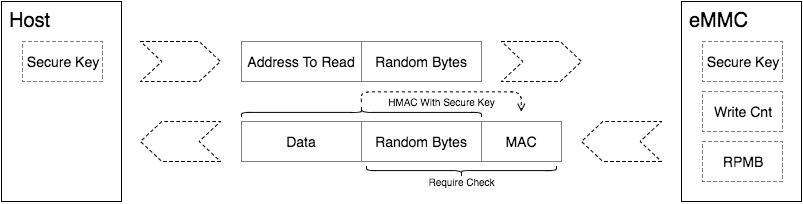
a. The Host initiates a read request to eMMC for RPMB, generating a 16-byte random number to send to eMMC.
b. eMMC reads the requested data from RPMB and uses the Secure Key to calculate a signature by concatenating the read data with the received random number using HMAC SHA-256. eMMC then sends the read data, the received random number, and the calculated signature back to the Host.
c. Upon receiving the RPMB data, random number, and signature, the Host first checks if the random number matches the one it sent. If they match, the Host uses the same Secure Key to calculate a signature for the concatenated data and random number. If the signature matches the one sent by eMMC, the Host can confirm that the data is the correct data read from RPMB and not forged by an attacker.
This reading process ensures that the Host correctly reads the data from RPMB.
3.4 RPMB Data Writing
The process for writing data to RPMB is as follows:
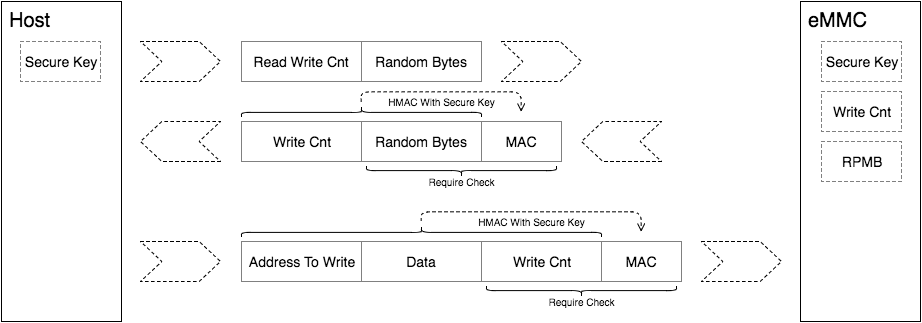
a. The Host follows the reading process above to read the Write Counter from RPMB.
b. The Host concatenates the data to be written with the Write Counter and calculates a signature, then sends the data, Write Counter, and signature to eMMC.
c. Upon receiving the data, eMMC first compares the Write Counter with the current value. If they match, it calculates a signature for the combination of data and Write Counter, then compares it with the signature sent by the Host. If the signatures match, authentication is successful, and the data is written to RPMB.
This writing process ensures that RPMB cannot be tampered with illegally.
4. User Data Area
The User Data Area (UDA) is typically the largest partition in eMMC and serves as the primary storage area in actual products.
4.1 Capacity Size
The capacity of UDA does not need to be set. After configuring the sizes of other partitions and deducting the capacity consumed by the Enhanced attribute, the remaining capacity is the capacity of UDA.
4.2 Software Partitioning
To manage data more effectively and meet different application needs, UDA is often further partitioned in actual products. The mainstream software partitioning technologies are MBR (Master Boot Record) and GPT (GUID Partition Table). The basic principles of these two partitioning technologies are similar, as shown in the image below:
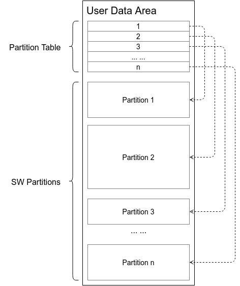
Software partitioning technology generally divides the storage medium into multiple areas, or SW Partitions, and maintains these SW Partitions through a Partition Table. Each entry in the Partition Table contains attributes such as the starting address and size of a SW Partition. When the software system starts, it scans the Partition Table to obtain information about the various SW Partitions on the storage medium, then loads these Partitions into the system for data access.
4.3 Area Attributes
The eMMC standard supports setting Enhanced attributes for a specific size area within UDA. Similar to the Enhanced attributes in GPP, the eMMC standard does not define the impact of setting Enhanced attributes on eMMC. The specific function of Enhanced attributes is defined by the chip manufacturer.
Examples of eMMC Partition Applications
In an Android mobile system, the presentation of various partitions is as follows:
- mmcblk0 is the block device for eMMC;
- mmcblk0boot0 and mmcblk0boot1 correspond to the two Boot Area Partitions;
- mmcblk0rpmb is the RPMB Partition;
- mmcblk0px represents the SW Partitions divided from UDA;
- If GPP exists, the names will be mmcblk0gp1, mmcblk0gp2, mmcblk0gp3, mmcblk0gp4;
root@xxx:/ # ls /dev/block/mmcblk0*
/dev/block/mmcblk0
/dev/block/mmcblk0boot0
/dev/block/mmcblk0boot1
/dev/block/mmcblk0rpmb
/dev/block/mmcblk0p1
/dev/block/mmcblk0p2
/dev/block/mmcblk0p3
/dev/block/mmcblk0p4
/dev/block/mmcblk0p5
/dev/block/mmcblk0p6
/dev/block/mmcblk0p7
/dev/block/mmcblk0p8
/dev/block/mmcblk0p9
/dev/block/mmcblk0p10
/dev/block/mmcblk0p11
/dev/block/mmcblk0p12
/dev/block/mmcblk0p13
/dev/block/mmcblk0p14
/dev/block/mmcblk0p15
/dev/block/mmcblk0p16
/dev/block/mmcblk0p17
/dev/block/mmcblk0p18
/dev/block/mmcblk0p19
/dev/block/mmcblk0p20
Each partition will be named according to its actual function.
root@xxx:/ # ls -l /dev/block/platform/mtk-msdc.0/11230000.msdc0/by-name/
lrwxrwxrwx root root 2015-01-03 04:03 boot -> /dev/block/mmcblk0p22
lrwxrwxrwx root root 2015-01-03 04:03 cache -> /dev/block/mmcblk0p30
lrwxrwxrwx root root 2015-01-03 04:03 custom -> /dev/block/mmcblk0p3
lrwxrwxrwx root root 2015-01-03 04:03 devinfo -> /dev/block/mmcblk0p28
lrwxrwxrwx root root 2015-01-03 04:03 expdb -> /dev/block/mmcblk0p4
lrwxrwxrwx root root 2015-01-03 04:03 flashinfo -> /dev/block/mmcblk0p32
lrwxrwxrwx root root 2015-01-03 04:03 frp -> /dev/block/mmcblk0p5
lrwxrwxrwx root root 2015-01-03 04:03 keystore -> /dev/block/mmcblk0p27
lrwxrwxrwx root root 2015-01-03 04:03 lk -> /dev/block/mmcblk0p20
lrwxrwxrwx root root 2015-01-03 04:03 lk2 -> /dev/block/mmcblk0p21
lrwxrwxrwx root root 2015-01-03 04:03 logo -> /dev/block/mmcblk0p23
lrwxrwxrwx root root 2015-01-03 04:03 md1arm7 -> /dev/block/mmcblk0p17
lrwxrwxrwx root root 2015-01-03 04:03 md1dsp -> /dev/block/mmcblk0p16
lrwxrwxrwx root root 2015-01-03 04:03 md1img -> /dev/block/mmcblk0p15
lrwxrwxrwx root root 2015-01-03 04:03 md3img -> /dev/block/mmcblk0p18
lrwxrwxrwx root root 2015-01-03 04:03 metadata -> /dev/block/mmcblk0p8
lrwxrwxrwx root root 2015-01-03 04:03 nvdata -> /dev/block/mmcblk0p7
lrwxrwxrwx root root 2015-01-03 04:03 nvram -> /dev/block/mmcblk0p19
lrwxrwxrwx root root 2015-01-03 04:03 oemkeystore -> /dev/block/mmcblk0p12
lrwxrwxrwx root root 2015-01-03 04:03 para -> /dev/block/mmcblk0p2
lrwxrwxrwx root root 2015-01-03 04:03 ppl -> /dev/block/mmcblk0p6
lrwxrwxrwx root root 2015-01-03 04:03 proinfo -> /dev/block/mmcblk0p13
lrwxrwxrwx root root 2015-01-03 04:03 protect1 -> /dev/block/mmcblk0p9
lrwxrwxrwx root root 2015-01-03 04:03 protect2 -> /dev/block/mmcblk0p10
lrwxrwxrwx root root 2015-01-03 04:03 recovery -> /dev/block/mmcblk0p1
eMMC Bus Protocol
eMMC Bus Interface
The eMMC bus interface is defined as shown in the figure below:
- CLK
The CLK signal is used to output a clock signal from the Host for data transmission synchronization and device operation driving.
Within one clock cycle, the CMD and DAT0-7 signals can support the transmission of 1 bit, i.e., SDR (Single Data Rate) mode. Additionally, the DAT0-7 signals can also be configured to DDR (Double Data Rate) mode, allowing the transmission of 2 bits within one clock cycle.
The Host can dynamically adjust the clock signal frequency during communication (note that the frequency range must meet the specifications defined). By adjusting the clock frequency, power-saving or data flow control (to avoid over-run or under-run) can be achieved. In some scenarios, the Host can also turn off the clock, for example, when eMMC is in a Busy state or after receiving data, entering the Programming State.
- CMD
The CMD signal is primarily used for the Host to send commands to eMMC and for eMMC to send corresponding responses back to the Host.
- DAT0-7
The DAT0-7 signals are mainly used for data transmission between the Host and eMMC. After powering on eMMC or performing a soft reset, only DAT0 can transmit data. After initialization, DAT0-3 or DAT0-7 can be configured for data transmission, meaning the data bus can be configured for 4 bits or 8 bits mode.
- Data Strobe
The Data Strobe clock signal is sent from eMMC to the Host, with a frequency equal to that of the CLK signal, used for synchronizing data reception on the Host side. The Data Strobe signal can only be enabled in HS400 mode, and when enabled, it can improve the stability of data transmission, eliminating the need for bus tuning.
eMMC Bus Model
In the eMMC bus, one Host can have multiple eMMC Devices. All communications on the bus are initiated by the Host with a Command, and the Host can only communicate with one eMMC Device at a time.
After the system powers on, the Host assigns addresses (RCA, Relative device Address) to all eMMC Devices one by one. When the Host needs to communicate with a specific eMMC Device, it first selects that eMMC Device based on the RCA; only the selected eMMC Device will respond to the Host’s Command.
1. Speed Modes
As the eMMC protocol versions have evolved, the bus speed has increased. To maintain compatibility with older eMMC Devices, all Devices will first enter a backward compatible mode (Backward Compatible Mode) after powering on or resetting. After initializing the eMMC Devices, the Host can follow a specific process to allow the Device to enter other high-speed modes, currently supporting several speed modes.
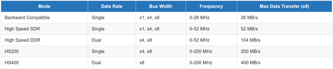
Note:
The Extended CSD byte[185] HS_TIMING register can configure the bus speed mode.
The Extended CSD byte[183] BUS_WIDTH register is used to configure the bus width and Data Strobe.
2. Communication Model
Communication between the Host and eMMC Device is initiated by the Host with a Command, and the eMMC Device returns a Response after completing the task specified by the Command.
2.1 Read Data
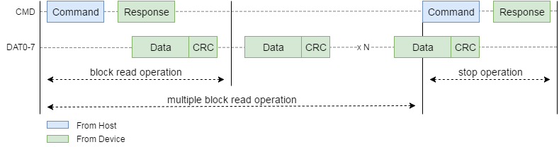
The process for the Host to read data from the eMMC Device is shown in the figure above.
If the Host sends a Single Block Read Command, the eMMC Device will only send one Block of data.
If the Host sends a command to set the Block Count before sending a Multiple Block Read Command, the eMMC Device will automatically end data transmission after sending the specified Block Count of data, without requiring the Host to send a Stop Command.
If the Host does not send a command to set the Block Count and sends a Multiple Block Read Command, the eMMC Device will continue to send data until the Host sends a Stop Command to stop data transmission.
Note: Data is read from the eMMC Device in blocks. The block size can be set by the Host or fixed at 512 Bytes, varying with different speed modes.
2.2 Write Data
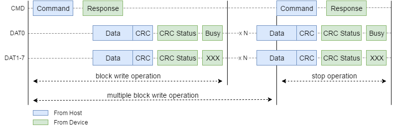
The process for the Host to write data to the eMMC Device is shown in the figure above.
If the Host sends a Single Block Write Command, the eMMC Device will only write the first Block of subsequent data into memory.
If the Host sends a command to set the Block Count before sending a Multiple Block Write Command, the eMMC Device will automatically end data reception after receiving the specified Block Count of data, without requiring the Host to send a Stop Command.
If the Host does not send a command to set the Block Count and sends a Multiple Block Write Command, the eMMC Device will continue to receive data until the Host sends a Stop Command to stop data transmission. After receiving a Block of data, the eMMC Device performs a CRC check and sends the result back to the Host via a CRC Token.
After sending the CRC Token, if the CRC check is successful, the eMMC Device will write the data to internal memory, at which point the DAT0 signal will be pulled low as a Busy signal. The Host will continuously monitor the DAT0 signal until it goes high before sending the next Block of data. If the CRC check fails, the eMMC Device will not write the data, and subsequent data in this transmission will be ignored.
Note: Data is written to the eMMC Device in blocks. The block size can be set by the Host or fixed at 512 Bytes, varying with different speed modes.
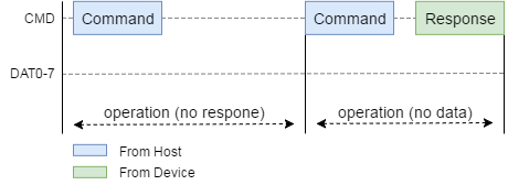
2.3 No Data
In communication between the Host and eMMC Device, some interactions do not require data transmission, and some interactions do not even require a response from the eMMC Device.
2.4 Command
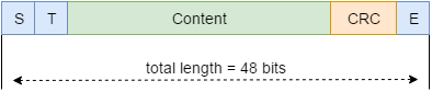
As shown in the figure above, the eMMC Command consists of 48 bits, with the following breakdown:

The Start Bit is fixed at “0”. In the absence of data transmission, the CMD signal remains high. When the Host sends the Start Bit onto the bus, the eMMC Device can easily detect this signal and begin receiving the Command.
The Transmission Bit is fixed at “1”, indicating that the direction of this data packet is from the Host to the eMMC Device.
The Command Index and Argument contain the specific content of the Command; different Commands have different Indexes and Arguments. For more details, refer to the eMMC Commands section.
The CRC7 is the CRC check value that includes the Start Bit, Transmission Bit, Command Index, and Argument content. The End Bit is a fixed end marker, set to “1”.
Note: CRC check is a method where the sender divides the data to be transmitted by a predetermined number and appends the remainder to the data. The receiver performs the same division and checks if the remainder matches the received remainder. If they do not match, it indicates that the data has changed during transmission. More details are not covered in this article; interested readers can refer to the CRC wiki for more information.
2.5 Response
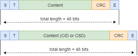
eMMC Response has two lengths of data packets, 48 bits and 136 bits.
The Start Bit, like the Command, is fixed at “0”. In the absence of data transmission, the CMD signal remains high. When the eMMC Device sends the Start Bit onto the bus, the Host can easily detect this signal and begin receiving the Response.
The Transmission Bit is fixed at “0”, indicating that the direction of this data packet is from the eMMC Device to the Host.
The Content contains the specific details of the Response; different Commands will have different Content. For more details, refer to the eMMC Responses section.
【Source: https://blog.csdn.net/u013686019/article/details/66472291】