4. Short Circuit of CAN L to Ground
When a short circuit occurs between CAN L and ground, due to the fault tolerance characteristics of the CAN bus, the entire CAN network may be unable to communicate or generate related fault codes.
However, for certain vehicle models, such as Haima, the fault tolerance characteristics of CAN L shorted to ground are relatively good, allowing the vehicle to operate normally, meaning there are no obvious abnormal phenomena from the customer experience perspective. However, from the diagnostic standpoint, it will affect the network transmission speed.
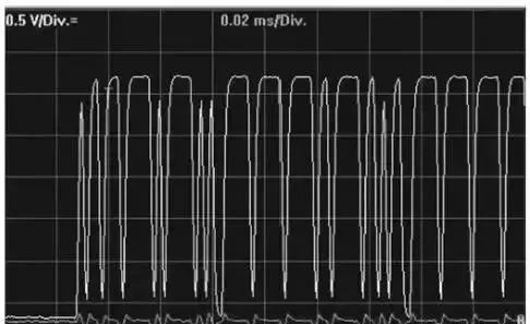
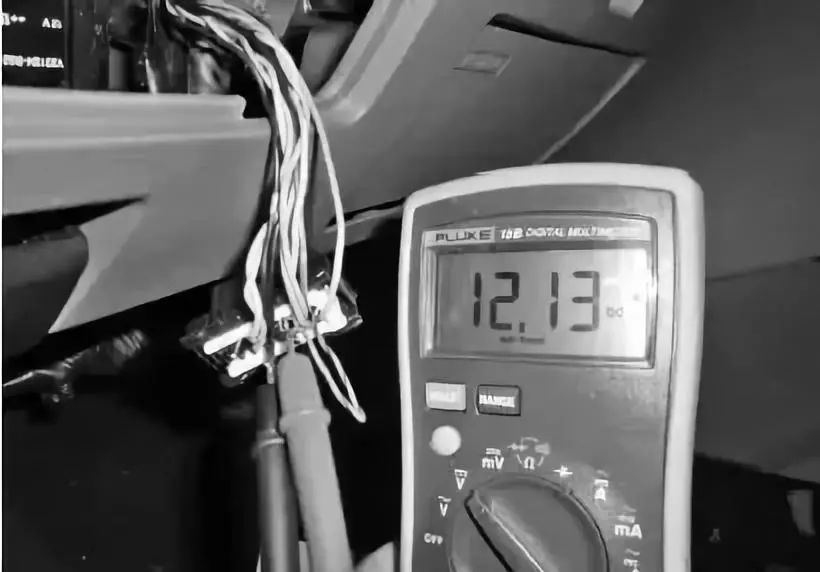
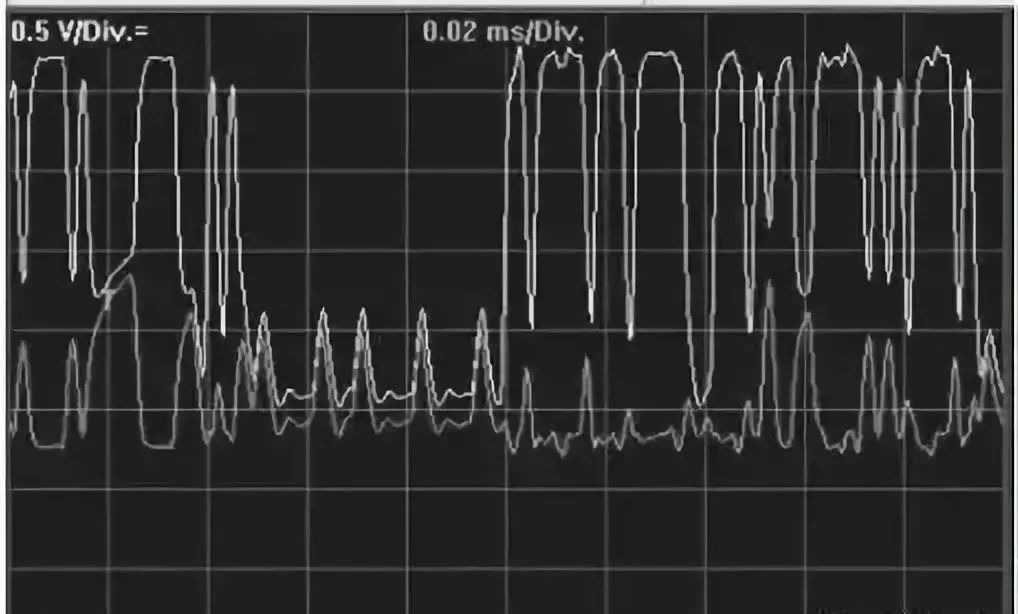
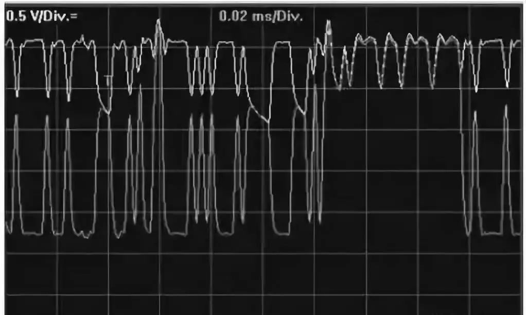
At this time, the voltage of CAN L is approximately 0V. The implicit voltage of the CAN H line is reduced to 0V, but the explicit voltage remains largely unchanged, thus elongating the waveform, which can still transmit data, illustrating the good fault tolerance characteristic of CAN L shorted to ground. The bus waveform for CAN L shorted to ground is shown in the following figure.
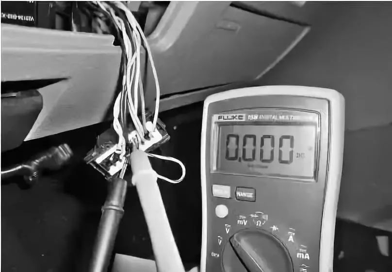
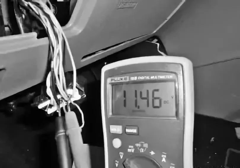
When measuring the voltage of the CAN wires, if the voltage of CAN L is 0V and CAN H is around 1V, it indicates this type of fault. The voltage of CAN L shorted to ground is shown in the following figure.
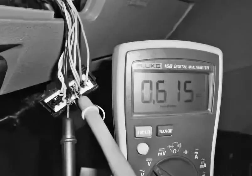
The voltage of CAN H when CAN L is shorted to ground is shown in the following figure.
Fault Cause: If the short circuit of CAN L to ground is not caused by an external ground short, then this fault may be caused by a damaged CAN transceiver inside the control module. The fault finding method is the same as above.
5. Short Circuit of CAN L to Power (Positive)
When a short circuit occurs between CAN L and power (positive), due to the fault tolerance characteristics of the CAN bus, the entire CAN network may be unable to communicate or generate related fault codes.
Since CAN L is shorted to power, the voltage of CAN H is also set to 12V. The bus waveform for CAN L shorted to power is shown in the following figure.
When measuring the voltage of the CAN wires, if both CAN L and CAN H are approximately 12V, it indicates this type of fault. The voltage of CAN L when shorted to power is shown in the following figure.
The voltage of CAN H when CAN L is shorted to power is shown in the following figure.
Fault Cause: If the short circuit of CAN L to power is not caused by an external power short, then this fault may be due to a damaged CAN transceiver inside the control module. The fault finding method is the same as above.
6. Open Circuit of CAN H
When the CAN H wire of a control module is open, it will cause that control module to be unable to communicate, but other control modules can still communicate. Other control modules may read the fault code of this faulty module. If multiple control modules experience an open circuit in their CAN H wires, the communication function of these control modules will be affected. The bus waveform for CAN H open circuit is shown in the following figure.
If the faulty control module has a terminal resistor, the resistance measurement method can be used for diagnosis. Measure the resistance between CAN H and CAN L at the diagnostic interface; if it changes to 120Ω, it indicates that one terminal resistor is open. If the faulty control module does not have a terminal resistor, then the continuity of the CAN wires of that control module needs to be measured.
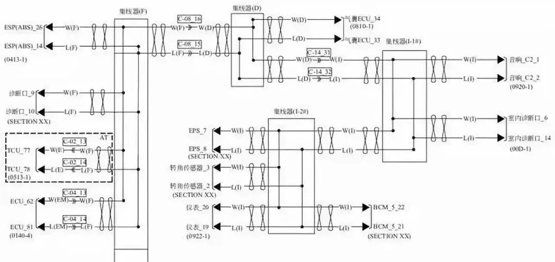
Replacing the control module involved with the fault code can quickly determine whether the fault is caused by that control module itself. Additionally, the network diagram should be used to locate breakpoints, as different locations of breakpoints will affect different components, and will also determine which control modules can be diagnosed by the diagnostic tool. The distribution of the CAN network and hubs is shown in the following figure.
7. Open Circuit of CAN L
When the CAN L wire of a control module is open, it will cause that control module to be unable to communicate, but other control modules can still communicate. Other control modules may read the fault code of this faulty module. If multiple control modules experience an open circuit in their CAN L wires, the communication function of these control modules will be affected.
If the faulty control module has a terminal resistor, the resistance measurement method can be used for diagnosis. Measure the resistance between CAN H and CAN L at the diagnostic interface; if it changes to 120Ω, it indicates that one terminal resistor is open. If the faulty control module does not have a terminal resistor, then the continuity of the CAN wires of that control module needs to be measured. The bus waveform for CAN L open circuit is shown in the following figure.
Replacing the control module involved with the fault code can quickly determine whether the fault is caused by that control module itself. Additionally, the network diagram should be used to locate breakpoints to accurately identify the cause and eliminate the fault.
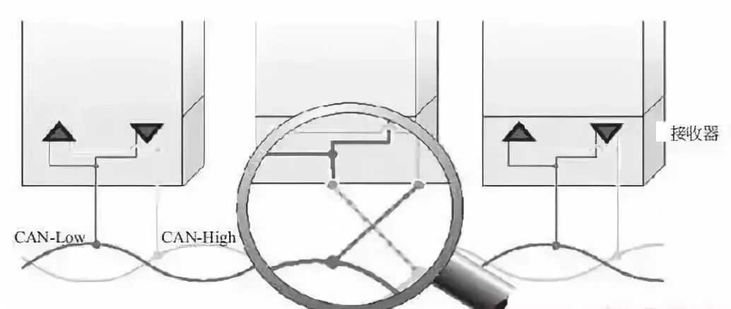
8. CAN L and CAN H Wires Reversed
When the CAN L and CAN H wires are reversed, generally, the control module with the incorrect connection will be unable to communicate, while other control modules will communicate normally. The schematic diagram of CAN L and CAN H wires reversed is shown in the following figure.
Measure the voltage at the pins of the CAN wires of the suspected faulty control module to verify whether the voltage is normal. Check the line connection against the CAN network diagram to determine if this fault exists. If so, repair the CAN network. Replacing the control module involved with the fault code can help determine whether the fault is caused by that control module.
Source: Electrical Control Knowledge Transfer