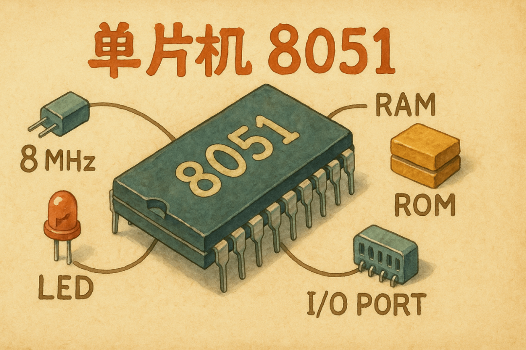
In embedded system design, we often need to use the General Purpose Input/Output (GPIO) pins of microcontrollers (MCUs) to drive peripheral devices such as LEDs and relays. I still remember that my first code in college was to control the blinking of an LED using the 8051 microcontroller. I wonder if the current university courses still include programming experiments with the 51 microcontroller, or if they have moved on to more advanced microcontrollers like the STM32 right from the start?
Here is a simple C code snippet to control the blinking of an LED using the 51 microcontroller (ps: this is not the first code I wrote in school, as the hard drive containing my code has been lost, along with many wonderful memories  ).
).
#include<reg52.h>           // Include the header file for 8051 special function register
sbit LED = P2^0;            // Define LED connected to P2.0 pin
void Delay(void);           // Delay function declaration
void main(void){    while(1)                // Infinite loop    {
        LED = 0;            // Turn on LED (active low)
        Delay();            // Delay
        LED = 1;            // Turn off LED (active high)
        Delay();            // Delay
    }}
// Software delay function
void Delay(void){    int j;    int i;    for(i=0; i<10; i++)    {
        for(j=0; j<10000; j++)        {
            // Empty loop to create delay        }
    }}
Since this was my first microcontroller code, I kept the program logic as simple as possible:
1. Header file inclusion: #include<reg52.h> includes the register definitions for the 8051 series microcontrollers.
2. Pin definition: sbit LED = P2^0; defines the P2.0 pin as the LED control pin.
3. Main function logic:
-
Using an infinite loop while(1)
-
LED = 0 turns on the LED (active low)
-
LED = 1 turns off the LED
-
Control the blinking frequency using the Delay() function
4. Delay function: A double for loop is used to create a software delay, where the program runs empty loops to consume instruction time. A better approach would be to use a timer to generate interrupts to control the LED blinking, allowing the MCU to handle other logical operations in the meantime.
This old 51 microcontroller code logic also applies to more modern and advanced STM32 microcontrollers, although STM32 initialization can be more complicated, requiring enabling the GPIO clock and setting the GPIO output mode, etc.
In terms of program logic, there is no difference between the 51 microcontroller and the STM32 microcontroller, but there are some nuances in the hardware circuit, especially when you are used to working with your own STM32 development board for experiments, and then switch to the school’s antique 51 microcontroller development board during lab assessments. The hardware-level differences between these two chips often leave students who are focused solely on coding a bit confused.

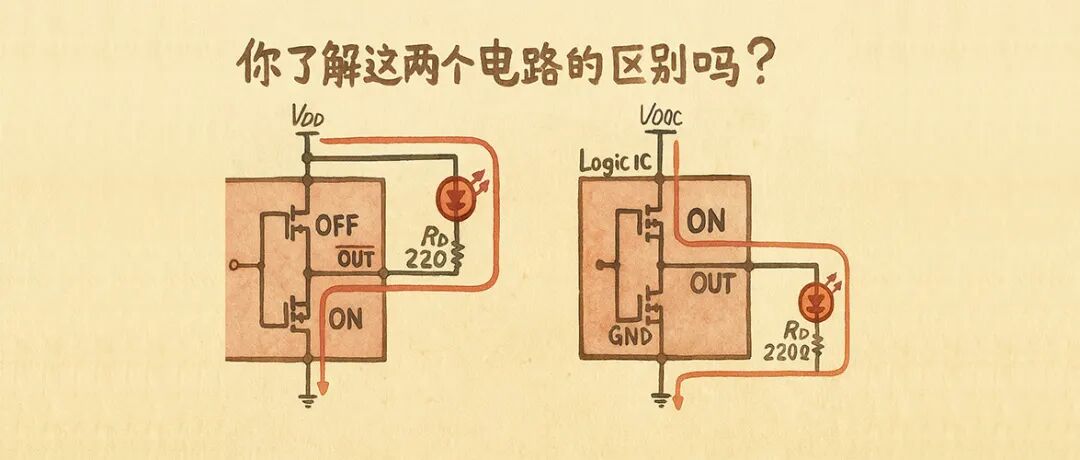
When using GPIO to light up an LED, a common question is whether the driving circuit should be designed to light up with a high level or a low level?
-
High-level logic driving: When the MCU pin outputs a high level (‘H’), current flows from the MCU to the LED, lighting it up.
-
Low-level logic driving: When the MCU pin outputs a low level (‘L’), current flows from the power supply through the LED to the MCU, lighting it up.
Intuitively, these two methods seem to be indistinguishable, at least for microcontrollers like the STM32, but for the 51 microcontroller, they differ in current driving capability.
8051 GPIO is “Quasi-bidirectional IO”
The classic 8051 microcontroller (specifically P1, P2, P3 ports) does not have a true push-pull structure. Its I/O ports are referred to as quasi-bidirectional ports. Its internal structure is asymmetrical:
-
A weak pull-up resistor.
-
A strong pull-down N-MOS transistor.
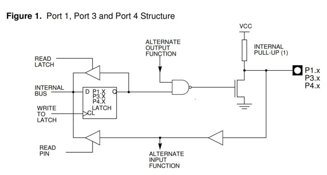
When a “1” (high level) is written to the GPIO pin of the 51 microcontroller: the lower N-MOS is turned off, and at this point, the pin level is pulled high only by the weak internal pull-up resistor. This “pull-up” action is very weak and can only provide a small amount of current.The maximum output current is typically only about 0.1-0.3mA, due to the weak pull-up resistor design (typical value around 20kΩ-50kΩ).
The maximum output current can be calculated as follows:
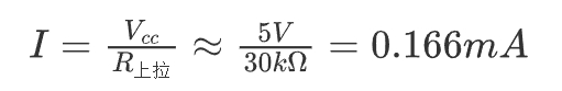
The actual current may vary slightly depending on the model and temperature, but is generally below 0.5mA. The weak internal pull-up resistor is completely unable to provide the milliamp-level current required to drive an LED, resulting in the LED being very dim or not lighting up at all.
When a “0” (low level) is written to the GPIO pin of the 51 microcontroller: the lower N-MOS is turned on, strongly pulling the pin level down to ground. This “pull-down” action is very strong and can “sink” a larger current, at the milliamp level, easily lighting up the LED, but it is not extremely powerful. The sinking current for the P0 port of the STC89C51 5V microcontroller is a maximum of 12 mA, while the sinking current for other I/O ports is a maximum of 6 mA. The sinking current for the P0 port of the STC89LE51 3V microcontroller is a maximum of 8 mA, while the sinking current for other I/O ports is a maximum of 4 mA.
It can be seen that the sinking current of the 51 microcontroller is not very strong, and can only directly drive low-power loads (such as low-brightness LEDs, small-sized digital tubes). If you need to drive relays, buzzers, etc., you need to connect external transistors or MOSFETs to amplify the current.
STM32’s “Push-Pull” Mode Has Strong Driving Current
 STM32 GPIO Push-Pull Mode Current Flow Diagram
When configured for output, the most commonly used mode for STM32 GPIO is the “Push-Pull” mode. Its name vividly describes its internal structure: it consists of a P-MOS transistor (upper transistor) and an N-MOS transistor (lower transistor).
-
Push: When a high level is needed, the upper P-MOS is turned on, and the lower N-MOS is turned off. The P-MOS transistor acts like a hand, actively and powerfully “pushing” the pin voltage towards the power supply (VDD), capable of providing (Source) a large current.
-
Pull: When a low level is needed, the lower N-MOS is turned on, and the upper P-MOS is turned off. The N-MOS transistor acts like another hand, actively and powerfully “pulling” the pin voltage towards ground (GND), capable of sinking (Sink) a large current.
Thanks to advancements in semiconductor technology, STM32 can equip each pin with a more powerful and intuitive true push-pull structure. Whether outputting a high or low level, a powerful transistor is actively working, providing and sinking nearly equal levels of current, resulting in strong and balanced driving capability.
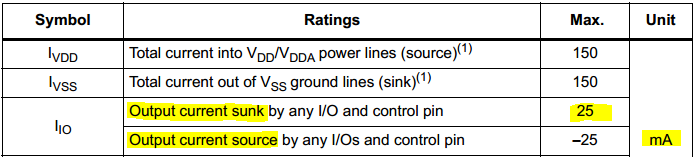
As shown in the current specifications table in the STM32 Datasheet, the maximum current for GPIO sourcing and sinking is both 25mA, which is sufficient to provide adequate brightness for LEDs.
Why is “Sinking Current” Sometimes More Powerful?
When the classic 8051 was first released, the technology at the time could not achieve high-density transistor integration, or in other words, photolithography of transistors on silicon wafers was relatively expensive. Therefore, the design wisdom of the classic 8051 was to use fewer transistors to achieve a clever, read-write “quasi-bidirectional” port, which was a highly cost-effective innovation at the time. Most CMOS logic ICs use a “push-pull” structure for their output stages, consisting of a P-channel MOSFET and an N-channel MOSFET.
-
When outputtinga high level, the upper P-MOS transistor is turned on, “pushing” the pin towards the power supply voltage (Vcc).
-
When outputtinga low level, the lower N-MOS transistor is turned on, “pulling” the pin towards ground (GND).
The key point is that due to the differences in semiconductor physical properties,the on-resistance of N-channel MOSFETs is usually lower than that of P-channel MOSFETs.
-
When “sinking” current from outside to inside, the internal voltage drop is smaller, allowing for a larger current to flow.
When “sourcing” current from inside to outside, the internal voltage drop is larger, limiting its output current capability.
In short, the classic 8051 microcontroller adopted a “weak pull-up resistor” + “strong pull-down N-MOS transistor” approach to save transistors, resulting in an asymmetrical driving current capability, requiring the use of “sinking current” to light up LEDs.
Due to STMicroelectronics’ excellent process with its own wafer fabrication, the “sinking current” and “sourcing current” capabilities of the STM32 microcontroller are consistent, both at a maximum of 25mA. However, some CMOS logic ICs, such as those from lesser-known manufacturers like the 74HC04 logic IC, may have stronger driving capability when using the “sinking current” method compared to the “sourcing current” method. (ps: we all understand the pain of purchasing generic ICs).
How to Confirm the Driving Capability of an IC?
As engineers, we cannot rely solely on experience. There are two methods to determine the specific driving capability of an IC:
-
Consult the Datasheet: The datasheet is the gold standard. You need to pay attention to the electrical characteristics, particularly
<span>V_OH</span>(high-level output voltage) and<span>V_OL</span>(low-level output voltage) parameters. These parameters are usually given under specific output current conditions (<span>I_OH</span>and<span>I_OL</span>). By using these values, you can estimate the equivalent on-resistance of the IC at high and low output levels and understand its maximum sinking/sourcing current capability. Remember not to exceed the current limits specified in the “Absolute Maximum Ratings”. -
Use SPICE Models for Simulation: For more precise analysis, look for SPICE models provided by the chip manufacturer. By building a test circuit in simulation software, you can visually obtain the complete I-V characteristic curve of the IC, providing accurate data support for your design.
Practical Considerations
Based on the above analysis, when designing peripheral circuits for microcontrollers, we should pay attention to the following points:
-
Prioritize using low-level logic driving: For loads that require larger currents or expect optimal performance (such as high-brightness LEDs, optocouplers, etc.), the design should prioritize low-level active, i.e., using the “sinking current” method.
-
Driving high-power loads: The current capability of MCU GPIO pins is limited (usually in the range of a few mA to tens of mA, with STM32 GPIO’s maximum current being 25mA). When driving motors, high-power relays, and other loads, direct connection is not allowed. External driver circuits, such as MOSFETs or dedicated driver ICs, must be used to amplify the current. In this case, the MCU pin can also drive the gate of an external N-MOSFET with a low level, which is usually simpler and more efficient than driving a P-MOSFET.
-
Carefully read the datasheet: The driving capabilities of GPIOs can vary significantly between different models and series of MCUs. Always read the datasheet of the target device carefully before designing to clarify its
<span>I_OL</span>and<span>I_OH</span>specifications. - Ensure that procurement does not buy generic ICs.
Finally, I wish everyone good luck in their designs, avoiding pitfalls and not being caught by generic ICs purchased through procurement.
#include<reg52.h>           // Include the header file for 8051 special function register
sbit LED = P2^0;            // Define LED connected to P2.0 pin
void Delay(void);           // Delay function declaration
void main(void) {     while(1)                // Infinite loop     {
         LED = 0;            // Turn on LED (active low)
         Delay();            // Delay
         LED = 1;            // Turn off LED (active high)
         Delay();            // Delay
     } }
// Software delay function
void Delay(void) {     int j;     int i;     for(i=0; i<10; i++)     {
         for(j=0; j<10000; j++)         {
             // Empty loop to create delay         }
     } }
#include<reg52.h> // Include the header file for 8051 special function register
sbit LED = P2^0; // Define LED connected to P2.0 pin
void Delay(void); // Delay function declaration
void main(void) { while(1) // Infinite loop {
LED = 0; // Turn on LED (active low)
Delay(); // Delay
LED = 1; // Turn off LED (active high)
Delay(); // Delay
} }
// Software delay function
void Delay(void) { int j; int i; for(i=0; i<10; i++) {
for(j=0; j<10000; j++) {
// Empty loop to create delay }
} }