Yesterday, I shared an article titled “The Evolution of Automotive CAN Bus,” which sparked a lot of interest among friends, prompting them to leave messages asking for related knowledge about the LIN bus used in automobiles.
Thus, I am sharing this article titled “The Evolution of Automotive LIN Bus” with everyone. I have modified the title myself. Based on everyone’s understanding habits, I have made some adjustments to the expressions in the article. This note is originally authored by Xiaomin.
As someone who has been in the industry for many years, revisiting what I thought I was already familiar with still brings new insights and realizations. I feel it is necessary to share this article once again with friends who love learning, hoping that this article can lead everyone to deepen their professional understanding.
For further reading, please click the title below to continue learning.
The Evolution of Automotive CAN Bus: A Journey Toward Professional Depth
Mount Everest
Overview
With the increasing number of electronic devices in automobiles, the market’s demand for a bus that costs less than CAN has become increasingly strong. Different car manufacturers have successively developed their own serial communication (UART/SCI) protocols to replace CAN in low-speed and less performance-demanding scenarios. Due to compatibility issues with protocols defined by different manufacturers, a joint working group was established in 1998 by five major European car manufacturers (BMW, Volkswagen Group, Audi Group, Volvo Cars, Mercedes-Benz), with technical support from Volcano Automotive Group and Motorola, to develop a serial communication bus aimed at networking sensors (Sensors) and actuators (Actuators) in the automotive electronic domain. The requirement for this bus system was to keep the protocol and timing control as simple as possible, allowing communication based on this bus even if low-end MCUs lack dedicated communication units. This bus is what this article introduces as the LIN bus.
The LIN (Local Interconnect Network) bus is a widely used serial communication protocol in automobiles. Its first complete version V1.3 was released in 2002, and in 2016, the LIN bus was officially listed as an international standard (ISO 17987). As the name suggests (emphasizing Local), it indicates that all devices on the bus are generally located in adjacent physical spaces (for example, in a car door). The regional subsystems (Cluster) constructed by the LIN bus are then connected to the upper-level CAN bus through ECUs (gateways, etc.).
LIN is suitable for applications with a maximum of 16 nodes and data rates of 20Kbps or less. The LIN bus allows for simple and fast networking, where the nodes on the bus are divided into one master and multiple slaves. The master is usually the ECU connected to the upper-level network, while the slaves are actuators, intelligent sensors, or switches that include a LIN hardware interface. The master controls the entire communication process on the LIN bus, and during communication, the slave clock must be synchronized with the master clock. The LIN bus topology is typically linear, meaning all devices are connected in a single line.
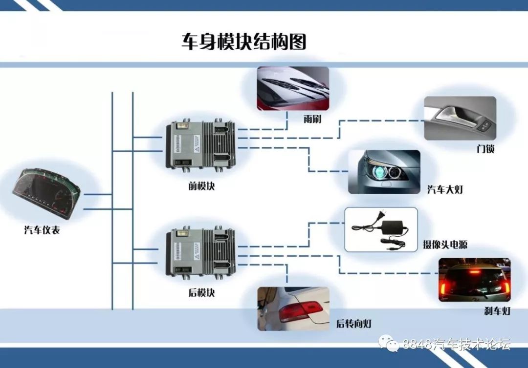
As a low-cost serial communication solution, the LIN bus is suitable for low-speed communication between distant nodes in automobiles and is also applicable in industrial control scenarios. LIN complements the functionalities and costs of the CAN bus. By using both, a hierarchical network architecture can be constructed within the automobile. In short, the LIN bus is akin to a reliable serial port in vehicles.
Standardization
↵
Historical Development
↵
1998/10: The concept of the LIN bus was first proposed at an automotive electronics conference in Germany; 1999/07: The first version V1.0 was released; 2002/12: V1.3 was released, mainly modifying the physical layer to improve compatibility between nodes; 2003/09: V2.0 was released, supporting the standardization of configuration and diagnostics, and defining node performance files, etc.; 2006/11: V2.1 was released, clarifying some content and correcting the configuration part, separating the transport layer and diagnostic parts into chapters; 2010/12: V2.2 was released, correcting some content and relaxing the bit sampling specifications; 2010/12: V2.2A was released, correcting the definition of the wake-up signal; 2016/08: Upgraded to the international standard ISO 17987 Part 1-7.
In addition, the SAE J2602 standard is the American version based on LIN V2.0.
↵
Standard Text
↵
In the 2016 released ISO 17987 Part 1-7 standard, its various parts are as follows:
-
ISO/CD 17987-1 General information and use case definition
-
ISO/CD 17987-2 Transport protocol and network layer services
-
ISO/CD 17987-3 Protocol specification
-
ISO/CD 17987-4 Electrical Physical Layer (EPL) specification 12V/24V
-
ISO/CD 17987-5 Application Programmers Interface (API)
-
ISO/CD 17987-6 Protocol conformance test specification
-
ISO/CD 17987-7 Electrical Physical Layer (EPL) conformance test specification
The assignment of LIN suppliers ID has been transferred from the previous CiA (CAN in Automation) to SAE (Society of Automotive Engineers) for management.
↵
Development Process
↵
The LIN protocol not only defines the standards for bus communication but also establishes a unified development process (Workflow) to quickly and easily build a network. As shown in Figure 1, the core component in this development process is the LDF (LIN Description File), which defines all communication features of the LIN network. Communication hosts can automatically generate all software components for the communication process based on the LDF. Additionally, the LDF can provide the necessary information for testing and measurement tools to analyze the LIN network.
The LIN Configuration Language Specification defines the process for creating the LDF, and the syntax for creation is relatively simple, allowing it to be generated manually or automatically through software tools. Since the LIN V2.0 specification, the additional node unified description language can clearly specify the communication features of commercial off-the-shelf nodes (Off-the-Shelf Nodes), and the node feature files described by this LIN Node Capability Language are called NCF (Node Capability File), which are essential for creating the system LDF in the LIN subnet (Cluster).
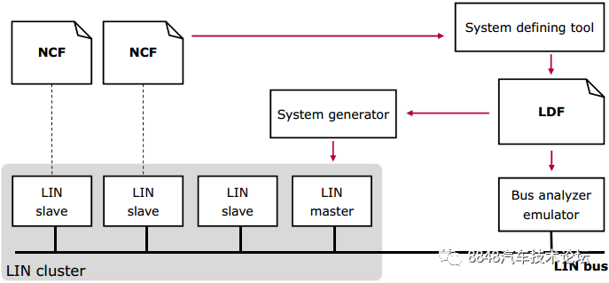
Figure 1. LIN Development Process
Application Characteristics
↵
The features of the LIN bus include:
-
Half-duplex communication based on UART/SCI, low-cost hardware interface;
-
Single master, up to 15 slaves, with the number of masters and slaves adhering to LIN protocol recommendations for compatibility responses;
-
In a typical LIN bus, the number of nodes is less than or equal to 12; in non-standard designs, the number of nodes can exceed 16;
-
SNPD (Slave Node Position Detection) allows for the assignment of node addresses after power-up;
-
Communication speed of 19.2Kbps @40m, with communication speeds reaching 20Kbps in LIN v2.2 (with EMC performance trade-offs, speeds up to 100Kbps are also possible in non-standard designs);
-
The transmission medium is an unshielded single electronic wire;
-
Guaranteed latency time;
-
Short message transmission, data lengths can be selected as 1, 2, 4, or 8 bytes;
-
Broadcast reception based on clock synchronization, with slaves not requiring oscillators or ceramic resonators;
-
Data checksum and error detection functions;
-
Ability to detect erroneous nodes;
-
Signal voltage referenced to battery voltage, around 12V
In summary, the advantages of the LIN bus are as follows:
-
Easy to use, with standard interface modules available on the market;
-
Lower device costs compared to CAN bus (and other buses);
-
More streamlined wiring;
-
Sufficiently reliable communication mechanisms;
-
Simple application expansion;
-
No licensing fees required
In low-speed applications with less bandwidth demand, LIN has a significant cost advantage and is a better alternative to CAN, but LIN cannot completely replace the CAN bus (speed + reliability). Generally, the LIN bus is mainly applied in automotive subsystems that do not significantly affect safety and overall vehicle performance, such as door and window controls, wipers, air conditioning, seat adjustments, and lighting. Figure 2 illustrates the application of the LIN bus in the roof/wiper area, where the Central ECU is the master, including four slaves: rearview mirror, door opener, rain/light sensor, and wiper. The master also serves as the Gateway module connecting to the chassis CAN, body CAN, and diagnostic CAN.
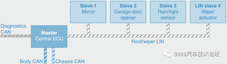
Figure 2. Example of LIN Bus Master and Slave Nodes
↵
Communication Mechanism
↵
Network Topology
↵
The topology of the LIN bus is a single-wire bus, which includes a single master and multiple slaves. The master includes master tasks (Master Task) and slave tasks (Slave Task), while slave nodes only include slave tasks, as shown in Figure 3.
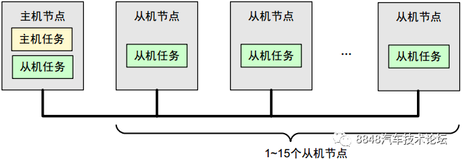
Figure 3. LIN Bus Topology Diagram
Master/Slave
↵
The LIN bus is a master-slave communication system. Only one master is allowed on the LIN bus, which controls all communication processes on the bus. Slaves can only send messages to the bus with the master’s permission. The master sends requests (frame headers, Frame Header) to the bus, and the relevant slaves or the master itself respond based on this frame header, forming the frames of the LIN bus (Frame), as shown in Figure 4.
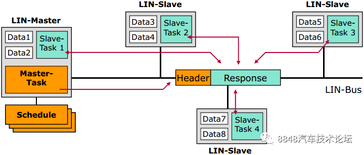
Figure 4. LIN Master Task & Slave Task
On the LIN bus, the master controls the transmission process of each message within the subnet. This bus access method is called delegated token access (Delegated Token). The advantage of the delegated token access method is that it can avoid conflicts during message transmission since the master fully coordinates and controls each message’s response request. The LIN bus master can plan data transmission on the bus based on a pre-set schedule (Schedule). Therefore, the delegated token bus access method is classified as a deterministic bus access method. The drawbacks of the delegated token access method are twofold: first, if the master fails, the entire bus communication fails, making this method unsuitable for applications with high safety requirements; second, since every communication process is controlled by the master, this method is not suitable for event-driven (Event-driven) communication, as slaves cannot automatically acquire bus access rights to send data. To compensate for this shortcoming, the LIN protocol includes additional frame types that can send messages without following the delegated token access method. There are four types of frames in the LIN bus: unconditional frames, event-triggered frames, sporadic frames, and diagnostic frames.
Master tasks include:
-
Scheduling the transmission order of frames on the bus
-
Monitoring data, handling errors
-
Providing a standard reference clock on the bus
-
Receiving wake-up commands sent by slave nodes
Slave tasks include:
-
Sending responses
-
Receiving responses
-
Ignoring responses
↵
Communication Scheduling
↵
As there is no communication controller, the LIN bus protocol is implemented in microcontrollers in the form of software components. The master and slaves correspond to master tasks and slave tasks, respectively, to realize the communication process on the bus. In simple terms, all nodes on the bus include slave tasks for receiving and sending messages, while the master includes additional master tasks to coordinate message sending and bus access permissions.
When the bus starts working, the master immediately activates the master tasks and periodically executes the message sending program specified in the schedule (Schedule). Table 1 illustrates the contents of the LIN bus schedule, which includes the message PID (Message Header) and start time for each process. The slave tasks are defined based on the characteristics specified in the LDF, responding to the tasks specified by the frame header, which include sending responses, receiving responses, or ignoring responses.
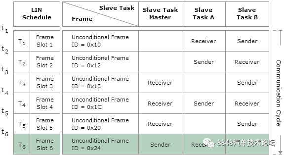
Table 1. LIN Bus Schedule
In message scheduling, the protocol defines the concept of Slot for a single message, where the duration of the slot must exceed the time for the frame header (Frame Header) and message response (Response) to ensure the message transmission is completed. A single frame is always transmitted completely within the same slot. Considering the impact of transceiver performance, the LIN protocol stipulates that the transmission time for a single message has a 40% allowance, meaning the minimum duration of a frame is 1.4 times its typical duration, as shown in Figure 5.
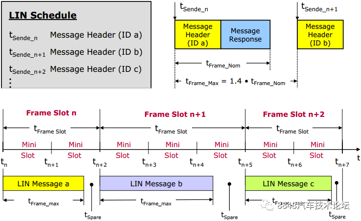 Figure 5. LIN Bus Schedule Timing
Frame Structure
↵
As mentioned earlier, the LIN bus frame consists of a frame header and a response. The master tasks are responsible for sending the frame header; the slave tasks receive the frame header, parse the information contained in it, and then decide whether to send a response, receive a response, or not respond at all. The frame header includes the synchronization interval segment, synchronization segment, and protected ID (PID, Protected Identifier) segment; the response segment includes the data segment and checksum (Checksum) segment. Figure 6 illustrates the frame structure of the LIN bus.
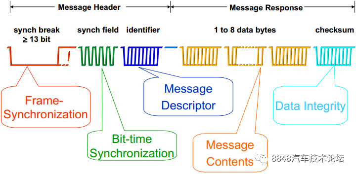
Figure 6. LIN Bus Frame Structure
Frame Header
↵
The synchronization interval segment (Sync Break Field) consists of a synchronization interval (Sync Break, tSYNBRK) and a synchronization interval segment delimiter (Break Delimiter, tDEL), as shown in Figure 7. The synchronization interval lasts for at least 13 bits (based on the bit rate of the master node) and is a dominant (low) level. Since all intervals in the frame or when the bus is idle should maintain a recessive (high) level, and no other field in the frame emits a dominant level exceeding 9 bits, the synchronization interval can mark the beginning of a frame. The delimiter of the synchronization interval lasts for at least 1 bit of recessive level. When the slave task receives the synchronization interval segment of the frame header, it uses the bit rate of the slave task’s node. When a dominant level persists for 11 bits on the bus, it is considered the beginning of the frame. When the slave node uses a high-precision clock, the identification threshold can be chosen as 9.5 bits.
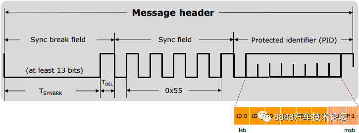 Figure 7. LIN Bus Frame Header
Before introducing the synchronization segment (Sync Field), let’s first explain the concept of the byte field (Byte Field), which consists of 10 bits, including 1 start bit (dominant) + 8 data bits + 1 stop bit (recessive), following a standard UART data transmission format, as shown on the left side of Figure 8. In a LIN frame, except for the synchronization interval segment, the subsequent segments are transmitted in the byte field format. In LIN frames, data transmission always sends the LSB (Least Significant Bit) first, followed by the MSB (Most Significant Bit).
The synchronization segment of LIN uses the falling edge as the judgment mark, sending the byte 0x55 (binary: 01010101b). The byte field of the synchronization segment is shown on the right side of Figure 8. Slave nodes can use lower-precision clocks, such as on-chip oscillators, which are relatively low in cost, and the resulting deviation from the master node’s clock needs to be adjusted through the synchronization segment. The adjustment results in the slave node’s data bit rate matching that of the master node. The clock rate of the master node is calculated based on the time difference between the first and last falling edges of the synchronization segment, divided by 8.
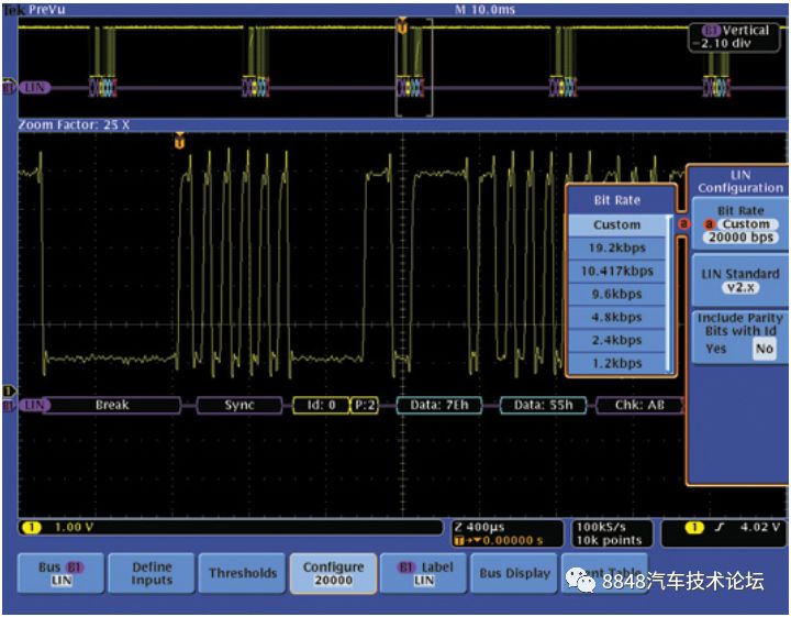 Figure 8. Concept of Byte Field and LIN Frame Synchronization Segment
Following the synchronization segment is the protected ID (PID, Protected Identifier) segment, where the first 6 bits are called the frame ID, generated based on the node LDF, identifying the type and destination of the frame. The slave task’s response to the frame header (receive/send/ignore response) is based on the frame ID. If the frame ID is transmitted incorrectly, it will result in the signal not reaching its destination correctly, making the frame ID quite important. Therefore, a 2 bit parity check is introduced, making the protected PID segment consist of the 6-bit frame ID and 2 bits of parity.
The frame ID ranges from 0 ~ 63, and based on different frame IDs, the frames are classified as follows:
-
Unconditional Frame (ID 0 ~ 59)
-
Each frame header corresponds to a message response
-
Transmitted in the fixed frame time slot assigned by the master
-
Diagnostic Frame (ID 60, 61)
-
Master requests frame ID = 60, ID = 0x3C
-
Slave responds frame ID = 61, ID = 0x3D
-
Reserved Frame (ID 62, 63)
-
User-defined ID = 62, ID = 0x3E
-
Future extension ID = 63, ID = 0x3F
The rules for generating parity bits for the PID are:
-
P0 = ID0 ⊕ ID1 ⊕ ID2 ⊕ ID4
-
P1 = ¬ (ID1 ⊕ ID3 ⊕ ID4 ⊕ ID5)
From the formulas, it can be seen that the PID will not be all 0 or all 1. Therefore, if a slave node receives “0xFF” or “0x00“, it can be determined as a transmission error.
↵
Response
↵
The data sent by the node is located in the data segment (Data Field), which contains 1 ~ 8 bytes, starting with the lowest numbered byte DATA1 and increasing in number. The data segment contains two types of data: signals (Signal) and diagnostic messages (Diagnostic messages).
Signals (Signal) are transmitted by the frame carrying the signal, where a single frame ID may correspond to one or more signals. When a signal is updated, its integrity must be ensured, and it cannot be partially updated. A signal is usually issued by a fixed node, referred to as the publisher node (Publisher), while one or more nodes receiving it are called the subscriber nodes (Subscriber).
Diagnostic messages (Diagnostic message) are transmitted by diagnostic frames, and the interpretation of the message content is determined by the data itself and the node’s state.
Note:
-
The protocol does not specify which part of the frame displays the information of the data length code; the content and length of the data are predefined by the system designer based on the frame ID.
-
The data on the bus is broadcast to all nodes, and any node can receive it, but not all signals are useful for every node. Subscriber nodes receive frame responses because their application layers will use these signals, while other nodes may ignore the frame responses as they do not require them. The publishing and subscribing of nodes are entirely implemented by software or configuration tools based on application layer needs. Generally, for a response in a frame, there is only one publishing node on the bus; otherwise, an error will occur. Event-triggered frames are an exception, which may have zero, one, or more publishing nodes.
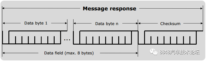 Figure 9. LIN Bus Frame Response
The checksum (Checksum) segment verifies the content transmitted in the frame. Checksums can be classified into standard checksums (Classic Checksum) and enhanced checksums (Enhanced Checksum). The choice between standard or enhanced checksums is managed by the master node, while the publishing and subscriber nodes determine which checksum to use based on the frame ID. The standard checksum only protects the data segment, while the enhanced checksum protects both the data segment and the frame ID segment. Nodes supporting LIN 1.X only support standard checksums, while LIN 2.X onwards support enhanced checksums. Additionally, diagnostic frames with frame IDs of 60/61 only support standard checksums.
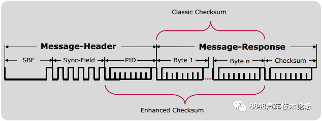 Figure 10. LIN Bus Frame Checksum
Frame Transmission Time
↵
The LIN bus frame consists of a frame header and a response, where the frame header includes the synchronization segment, frame ID segment, and two bits of parity. The longest response data segment is 8 Byte, as shown in Figure 11. LIN’s information transmission is based on the SCI interface, where each byte field includes 8 bit data, 1 bit start bit, and 1 bit stop bit. If the synchronization interval segment is 13 bit dominant bits + 1 bit recessive bit, then the frame header counts as 34 bit; the response, including the data segment and checksum segment, varies in length, with the shortest response being 20 bit (data segment 1 Byte) and the longest being 90 bit (data segment 8 Byte). In summary, the longest frame of the LIN bus is 124 bit (data segment 8 Byte), and the shortest is 54 bit (data segment 1 Byte). The formula for calculating the rated transmission time of a frame is as follows:

Where: n is the number of bytes in the data segment, and tBit is the inverse of the baud rate, for example, (19.2 kBit/s)^-1 = 52.1 us
 Figure 11. LIN Bus Frame Rated Transmission Time
The LIN protocol stipulates that the maximum transmission time for a frame is 1.4 times the rated transmission time, reserving 40% of the time for frame transmission. This feature considers the varying performance of node devices on the bus, allowing nodes not to execute commands immediately upon receiving them. In other words, the protocol allows nodes to delay sending the next UART character, but the total delay time cannot exceed 40% of the rated value. The delay time includes two types: Interbyte Space and Response Space. Their positions in the frame are illustrated in Figure 12.
 Figure 12. LIN Bus Frame Maximum Transmission Time
In summary, when setting the bus schedule (Figure 5), it is necessary to consider the frame transmission time to ensure that each step has sufficient time allowance.
↵
Frame Signal Waveform
↵
Figure 13 shows an example of the LIN bus frame signal waveform captured using a Tektronix oscilloscope. More debugging methods can be found in the link.
 Figure 13. Example of LIN Bus Frame Waveform
Frame Types
↵
Data transmission on the LIN bus includes 4 different frame types: unconditional frames, event-triggered frames, sporadic frames, and diagnostic frames (the reserved frame will not be mentioned here…).
↵
Unconditional Frame
↵
Frame ID 0 ~ 59. The unconditional frame (Unconditional Frame) has a single publishing node, where the frame header is unconditionally responded to regardless of whether the signal changes. Unconditional frames are transmitted in the fixed frame time slot assigned by the master. Once a frame header is sent on the bus, a slave task must respond (i.e., unconditionally send a response).
↵
Event-Triggered Frame
↵
Frame ID 0 ~ 59. The event-triggered frame (Event-triggered Frame) is used by the master node to query whether the signals of the slave nodes have changed (event) within a frame time slot. When multiple publishing nodes exist, conflicts are resolved through a collision resolving schedule (Collision Resolving Schedule). When the frequency of signal changes from slave nodes is low, the master task polling each signal will occupy a certain bandwidth. To reduce bandwidth usage, the concept of event-triggered frames is introduced. The first byte of data for the same PID in the event-triggered frame corresponds to that in the unconditional frame. The slave only sends a response when its own data changes, and if no slave responds on the bus, the response part of this frame is empty. If more than one slave responds on the bus, a conflict occurs, and the master polls all slaves by sending unconditional frames to resolve the conflict.
Figure 14 illustrates the schedule of the event-triggered frame. The upper half of the figure shows the situation without conflicts, where the master sends an event-triggered frame, and only slave 1 has a signal change, thus sending a response on the bus (Event A); the lower half of the figure shows the situation with conflicts, where the master sends an event-triggered frame, and both slave 2 and slave 4 have signal changes, thus both sending responses on the bus, resulting in a conflict. The master then executes the conflict resolution schedule by sending unconditional frames to poll all slaves, thus sequentially reading the Event B from slave 2 and Event D from slave 4.
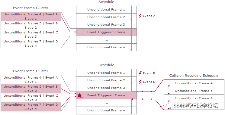 Figure 14. Event-Triggered Frame
The typical application of the event-triggered frame is to poll the switch status of four car doors. Instead of polling each door separately using unconditional frames, it is more efficient to inquire all four doors simultaneously. If one of the doors opens (an event occurs), that door will respond to the inquiry, i.e., event-triggered. This approach reduces bandwidth usage but may result in two phenomena: first, when no doors are opened, there are no node responses—event-triggered frames allow for a frame with only a header and no response; the second situation is a conflict, where two or more doors are opened simultaneously, and multiple nodes respond to the frame header without being considered an error. When a conflict occurs, the master node re-polls, which may increase response time, but since event-triggered frames are designed to handle low-probability events, it ultimately saves bandwidth.
↵
Sporadic Frame
↵
Frame ID 0 ~ 59. The sporadic frame (Sporadic Frame) is initiated by the master node to send a frame to the bus when its own signal changes within the same frame time slot. When multiple associated response signals change, arbitration is performed based on pre-set priorities. Sporadic frames are mainly used for the master to send information that does not change frequently, which can be understood as an event-triggered frame for the master. Similar to event-triggered frames, the responses of sporadic frames are also associated with a group of unconditional frames.
The transmission of sporadic frames may result in 3 situations:
-
When the associated unconditional frames do not have any signal changes, the time slot remains silent, and the master node does not need to send the frame header;
-
When one of the associated unconditional frames has a signal change, it sends the response part of that associated unconditional frame, as shown in the upper half of Figure 15;
-
If two or more associated unconditional frames have signal changes, the one with the higher priority gets to send the response, while the lower priority frames must wait for the next sporadic frame header to send their responses. Since the master node is the only publishing node, it knows the priority levels of each associated signal in advance, thus preventing conflicts during transmission, as shown in the lower half of Figure 15.
The introduction of sporadic frames and event-triggered frames aims to make the LIN bus communication mechanism more flexible, allowing messages to be transmitted only when signals change or remain unchanged, effectively improving communication efficiency on the bus.
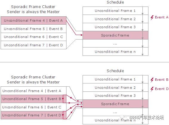 Figure 15. Sporadic Frame
Diagnostic Frame
↵
The diagnostic frame includes the master request frame and the slave response frame and is mainly used for configuration, identification, and diagnosis. Diagnostics are based on the ISO 15765-2 transmission standard and the ISO 14229 UDS (Uniform Diagnostic Services) standard. The frame ID for the master request frame is 0x3C, and the publishing node for the response part is the master node, typically used for diagnostic requests or configuring slaves; the frame ID for the slave response frame is 0x3D, with the publishing node for the response part being the slave node, generally for diagnostic responses. The data segment is defined as 8 bytes, and standard checksums are used throughout. The frame header and response direction of the diagnostic frame are shown in Figure 16.
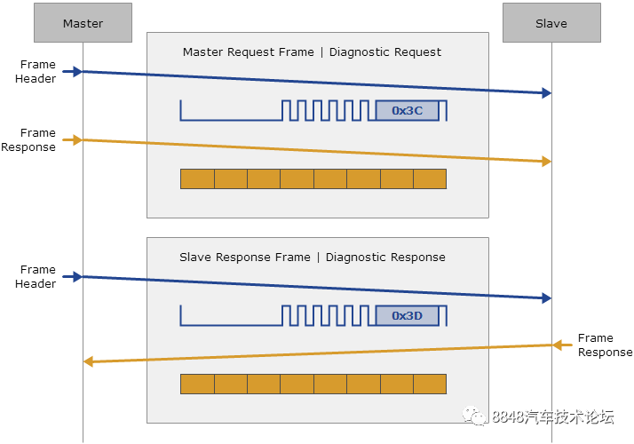 Figure 16. Diagnostic Frame
Status Management
↵
Status management of the LIN bus mainly refers to the sleep and wake-up of the network. The protocol specifies four states for slaves: off, initialization, operation, and sleep. The switching relationships between each state are shown in Figure 17. Upon powering up the system, the slave completes initialization within 100ms, then enters the operational state. The master can command a slave to enter sleep mode using the Go-to-Sleep command in the master request frame (DAT0 = 0x00, DAT1-7 = 0xFF). Slaves can also enter sleep mode within 4 to 10s after no activity on the bus.
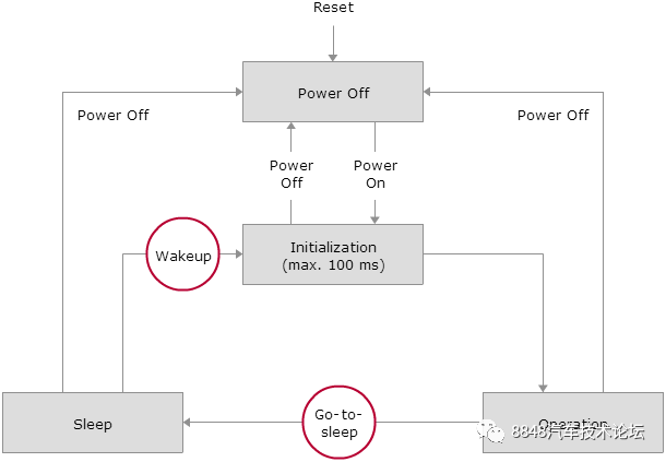 Figure 17. LIN Bus State Machine
Both the master and slaves can wake up the entire network, with the wake-up signal being a dominant signal lasting between 250us and 5ms. All nodes immediately exit sleep mode upon detecting the wake-up signal, initialize, and enter the operational state within a maximum of 100ms. If a node sends a wake-up signal and does not receive any commands (frame headers) on the bus within 150 to 250ms, it can resend the wake-up signal. A wake-up signal can be sent up to 3 times, and after three attempts, it must wait at least 1.5s before sending the wake-up signal again. Figure 18 illustrates the wake-up process of the LIN bus.
Hardware Circuit
↵
Power Supply & Signal Level
↵
The LIN bus requires that all nodes have the same signal voltage, with the signal voltage referenced to the transceiver’s supply voltage VSUP. Levels below 40% of VSUP are considered dominant (Dominant), i.e., “0“, while levels above 60% of VSUP are considered recessive (Recessive), i.e., “1“. The meanings of dominant/recessive here are consistent with those defined for the CAN bus, implementing a “line AND” logic: when one or more nodes on the bus send a dominant level, the bus presents a dominant level; the bus only presents a recessive level when all nodes send a recessive level or do not send any information (the bus defaults to a recessive level when sending any information), meaning dominant levels take precedence.
Considering voltage drops on the transmission line, the LIN protocol requires that the low level of the driver be below 20% of VSUP and that the high level be above 80% of VSUP to ensure sufficient margin when the receiver determines high and low levels.
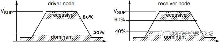 Figure 19. LIN Bus Voltage Levels
VSUP refers to the power supply voltage of the bus transceiver, and it should not be confused with the battery voltage (VBAT). Considering the voltage drop from the battery into the ECU unit in the power filtering (diodes, etc.) circuit, VSUP must be less than the battery voltage VBAT, as shown in Figure 20.
 Figure 20. Difference Between External Power Supply VBAT and Internal Power Supply VSUP
Transceiver
↵
The LIN bus transceiver essentially functions as a bidirectional level converter. The LIN specification requires the bus transceiver to withstand ±11.5% supply voltage fluctuations and reference point voltage fluctuations, as well as tolerate a potential difference of 8% between the supply and reference points. In less demanding situations, simple transceiver circuits can be used, as shown in Figure 21.
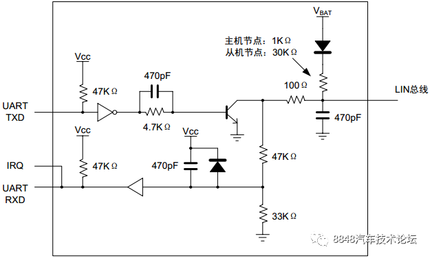 Figure 21. Simple LIN Transceiver Circuit
Termination Resistors
↵
To achieve the “line AND” characteristic, the LIN protocol specifies termination resistors for master and slave nodes, where one end of the termination resistor connects to the LIN bus, and the other end is connected through a series diode. The master termination resistor is 1K (range: 0.9 ~ 1.1K), and the slave termination resistor is 30K (range: 20 ~ 60K). As shown in Figure 22, the series diode is necessary to prevent power backflow on the LIN bus when the ECU power is disconnected.
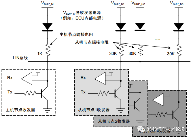 Figure 22. LIN Bus Termination Resistors
All LIN nodes are connected in parallel, forming the equivalent circuit shown in Figure 23. Here, the bus load resistance equals the parallel equivalent resistance of the termination resistors of each node, and the bus load capacitance equals the parallel equivalent capacitance of the input capacitance of each node and the distributed capacitance of the bus. The bus resistance determines the power and power consumption of the transceiver driver stage during communication; the bus capacitance can absorb noise interference from the surrounding environment. The RC filter formed by the bus resistance and capacitance also helps control the slew rate.
To ensure normal communication under the worst conditions, the LIN specification not only limits the termination resistance, capacitance, and time constant of the nodes but also stipulates that the typical values of the termination capacitance for the master/slave are 220pF. The termination capacitance for the master/slave can be adjusted based on specific applications to meet EME/EMI performance, with the slave termination capacitance having a limited adjustable range, mainly achieved by adjusting the master capacitance. Some transceivers specify the master as 1nF and the slave as 220pF, referring to the transceiver application manual for specifics. The protocol also states that the LIN bus length should not exceed 40 meters, and the maximum number of nodes in a LIN network should not exceed 16. Since the termination resistors connect the power supply and the LIN bus, significant current can flow through the termination resistors when a short circuit occurs on the LIN bus, leading to considerable power consumption.
 Figure 23. Bus Equivalent Circuit
Comparison
↵
This chapter compares the characteristics of LIN with other commonly used communication buses such as CAN, UART, and I2C, as shown in Table 2.
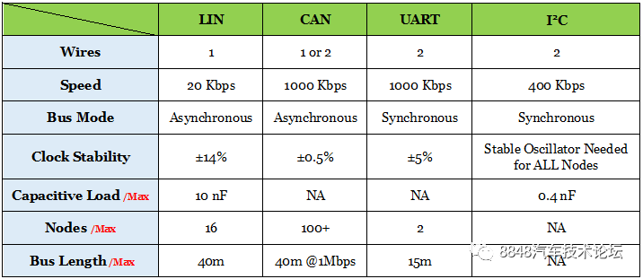 Table 2. Comparison of LIN with Other Communication Buses
[End of Full Text]