
1. Introduction to RS485
Smart instruments have developed alongside the maturity of microcontroller technology in the early 1980s, and now the global instrument market is largely dominated by smart instruments. The primary reason for this is the need for enterprise informatization, where a necessary condition for selecting instruments is the presence of a network communication interface. Initially, data was output as simple analog signals, and later the RS232 interface was used, which allowed point-to-point communication but did not support networking. The emergence of RS485 solved this problem. Below, we will briefly introduce RS485.
2. RS485 Interface
RS485 uses differential signaling with negative logic, where +2V to +6V represents “0” and -6V to -2V represents “1”.
RS485 can be wired in two-wire or four-wire configurations. The four-wire configuration only supports point-to-point communication and is rarely used now; the two-wire configuration is more common, allowing a maximum of 32 nodes to be connected on the same bus topology.
Typically, RS485 communication networks use a master-slave communication method, where one master controls multiple slaves. In many cases, a simple twisted pair is used to connect the “A” and “B” terminals, while neglecting the signal ground connection. This method can work in many situations but poses significant risks for two reasons:
(1) Common Mode Interference: RS-485 uses differential signaling, which does not require a reference point to detect signals; the system only needs to detect the potential difference between the two wires. However, it is often overlooked that transceivers have a certain common mode voltage range, which is -7 to +12V for RS-485 transceivers. Only when this condition is met can the entire network function correctly. If the common mode voltage exceeds this range, it can affect the stability and reliability of communication and may even damage the interface.
(2) EMI Issues: The common mode portion of the transmitted signal requires a return path. Without a low-resistance return path (signal ground), it will radiate back to the source, causing the entire bus to act like a large antenna radiating electromagnetic waves.
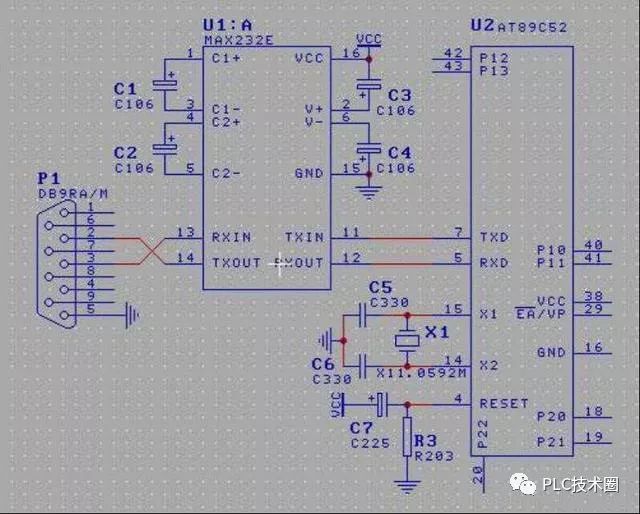
Since PCs typically only come with RS232 interfaces, there are two methods to obtain RS485 circuits on a PC:
(1) Use an RS232/RS485 converter circuit to convert the RS232 signals from the PC’s serial port to RS485 signals. For complex industrial environments, it is best to choose surge-protected products with isolation.
(2) Use a PCI multi-serial port card that directly outputs RS485 signals.
3. RS485 Cables
In general situations, ordinary twisted pair cables are sufficient, but in higher-demand environments, shielded coaxial cables can be used. When using RS485 interfaces, the maximum cable length allowed for data signal transmission from the RS485 interface to the load is inversely proportional to the baud rate of signal transmission. This length is mainly affected by signal distortion and noise.
Theoretically, the maximum transmission distance of RS485 can reach 1200 meters, but in practical applications, the transmission distance is usually shorter, depending on the surrounding environment. During transmission, repeaters can be used to amplify the signal, with a maximum of eight repeaters allowed, meaning the theoretical maximum transmission distance of RS485 can reach 9.6 kilometers. If long-distance transmission is truly needed, optical fibers can be used as the transmission medium, with a photoelectric converter at each end. Multi-mode fibers have a transmission distance of 5 to 10 kilometers, while single-mode fibers can reach up to 50 kilometers.
4. RS485 Networking
Network topology generally adopts a terminal-matched bus structure and does not support ring or star networks. When constructing a network, the following points should be noted:
(1) Use a twisted pair cable as the bus, connecting each node in series. The lead lengths from the bus to each node should be kept as short as possible to minimize the impact of reflected signals on the bus signals. Some network connections may work correctly at short distances and low speeds, but as communication distance increases or communication rates rise, the negative effects will become more severe, primarily due to signal reflections at the ends of branches that combine with the original signal, degrading signal quality.
(2) Ensure continuity of the bus’s characteristic impedance to avoid signal reflections at discontinuities. Common situations that cause discontinuities include using different cables for different segments of the bus, having too many transceivers installed closely together on a single segment, or having excessively long branches extending from the bus.
In summary, a single, continuous signal channel should be provided as the bus.
Another important issue during RS485 networking is the terminal load resistor. In cases where there are few devices and short distances, the network can function well without terminal load resistors; however, performance will degrade with increased distance. Theoretically, sampling at the midpoint of each receiving data signal can allow for no matching as long as reflected signals are sufficiently attenuated by the time sampling begins. When the signal rise or fall time exceeds three times the time required for the signal to travel unidirectionally along the bus, matching may be unnecessary.
Typically, terminal matching uses terminal resistors, with RS-485 requiring terminal resistors at both the beginning and end of the bus cable. The terminal resistance in an RS-485 network is 120Ω, which matches the characteristic impedance of the cable since most twisted pair cables have a characteristic impedance of approximately 100 to 120Ω. This matching method is simple and effective but has a drawback: the matching resistors consume significant power, making it unsuitable for systems with strict power limitations. An alternative, more power-efficient matching method is RC matching, which uses a capacitor to block DC components, saving most power. However, selecting the capacitor’s value is challenging, requiring a compromise between power consumption and matching quality. Another method uses diodes for matching; although this does not achieve true “matching,” it utilizes the clamping effect of diodes to quickly attenuate reflected signals, significantly improving signal quality and saving energy.
In the past two years, some companies have completed the implementation of enterprise informatization, establishing local area networks that extend to every office and control room in factories. They have introduced serial port servers to replace multi-serial port cards, primarily leveraging existing LAN resources to reduce wiring costs, effectively placing multi-serial port cards in the field via TCP/IP.
Differences Between RS485 and Other Bus Networks:
We categorize industrial networks into three types: RS485 networks, HART networks, and fieldbus networks.
HART Network: HART is a transitional bus standard proposed by Emerson, which superimposes digital signals on 4-20mA current signals. The physical layer uses BELL202 frequency shift keying technology to achieve partial functionality of smart instruments. However, this protocol is not a truly open standard; joining its foundation incurs fees, and the technology is primarily monopolized by a few large foreign companies. Although some domestic companies have made progress in recent years, they have not reached the level of foreign companies. A significant portion of smart instruments now includes HART capability, but domestically, this functionality is rarely utilized beyond parameter settings via handheld devices, lacking networked device monitoring. In the long term, due to low communication speeds and networking difficulties, the procurement volume of HART instruments is expected to decline. However, since HART instruments have been around for over a decade, they are still widely used, providing significant opportunities for system integrators.
Fieldbus Network: Fieldbus technology is one of the hot topics in automation technology development today, often referred to as the LAN of the automation field. Its emergence marks the beginning of a new era in automation control technology. Fieldbus networks connect instruments in the control field with control devices in the control room via digital, serial, multi-station communication. Its key feature is the ability to support bidirectional, multi-node, bus-based digital communication. Fieldbus technology has become a focal point for automation and instrumentation development internationally, revolutionizing traditional control system structures and advancing automated systems toward greater intelligence, digitization, informatization, networking, and decentralization, forming a new type of integrated distributed control system—Fieldbus Control System (FCS). However, various fieldbus standards currently coexist without a unified standard, and it is unclear when a unified standard will emerge, with technology still maturing. Additionally, the variety of fieldbus instruments available is limited, and prices tend to be high, leading most end users to adopt a wait-and-see approach, preferring to wait for technology maturity before considering implementation.
RS485 Network: RS485/MODBUS is a popular networking method today, characterized by its simplicity and convenience. Many instruments now support RS485, especially in the oil industry, where RS485/MODBUS is predominant. Instrument manufacturers are increasingly supporting RS485/MODBUS due to the difficulty and high cost of obtaining conversion ports for legacy HART instruments. RS485 conversion interfaces are much cheaper and more varied. At least in the low-end market, RS485/MODBUS will continue to be the primary networking method.
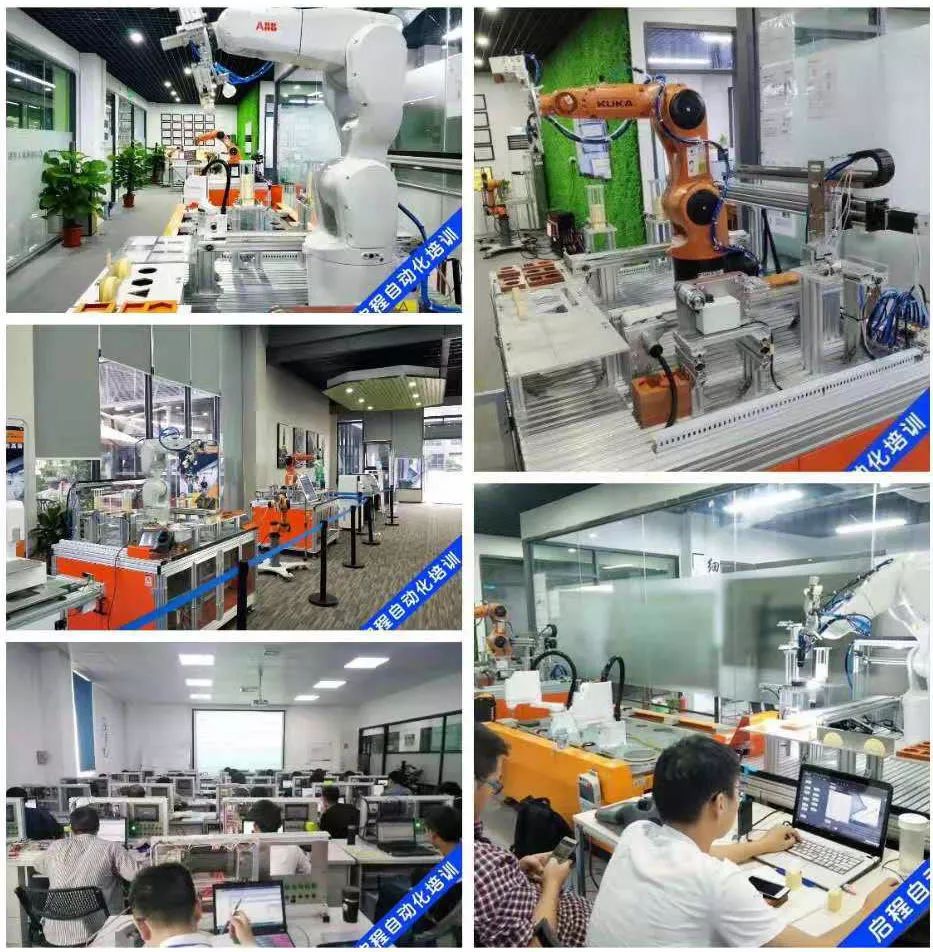
About Us: Qicheng Automation Training, China’s leading provider of industrial robot training services.
Contact Number: 13809869603
Training Programs:Robotics + PLC System Integration + Machine Vision
Special Services: 3000 square meters training center + job placement + industry-leading curriculum
Address: Shajing Innovation Park, Baoan District, Shenzhen

Contact the Teacher on WeChat for Course Details
Click to view before leaving.