Due to changes in the public account’s push rules, please click “Read” and add “Star” to get exciting technical shares as soon as possible.
Source from the internet, please delete if infringing
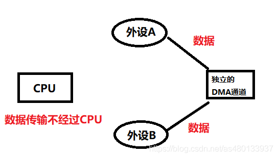
DMA, short for Direct Memory Access, is a method for transferring data directly between memory and peripherals without CPU intervention.DMA transfers data from one address space to another, providing high-speed data transfer between peripherals and memory or between memory and memory.We know that the CPU has many functions such as transferring data, computing, and controlling program flow, the core of system operation is the CPU.The CPU is constantly handling a large number of tasks, but some tasks are not that critical, such as data copying and storage. If we allocate some of the CPU’s resources to handle other complex computational tasks, wouldn’t that make better use of the CPU’s resources?Therefore: transferring data (especially large amounts of data) can be done without CPU involvement. For example, if we want to copy data from peripheral A to peripheral B, we just need to provide a data path for the two peripherals, allowing data to be copied from A to B without CPU processing.
DMA is designed based on the above concept, addressing the issue of excessive CPU resource consumption during large data transfers. With DMA, the CPU can focus more on practical operations – calculations, control, etc.
DMA Definition:
DMA provides high-speed data transfer between peripherals and memory or between memory and memory without CPU intervention. Data can be moved quickly through DMA, saving CPU resources for other operations.
DMA Transfer Modes
DMA’s role is to achieve direct data transfer, eliminating the need for CPU registers in traditional data transfer. It primarily involves four types of data transfers, which are fundamentally the same, transferring data from one area of memory to another (the data registers of peripherals are essentially storage units of memory). The four types of data transfers are as follows:
Peripheral to Memory
Memory to Peripheral
Memory to Memory
Peripheral to Peripheral
DMA Transfer Parameters
We know that for data transfer, we first need 1. the source address of the data, 2. the target address for data transfer, 3. the amount of data to be transferred, and 4. the transfer mode indicating how many transfers will occur. These four parameters are the core requirements for DMA.When the user sets the parameters, mainly involving source address, target address, and data transfer amount, the DMA controller will initiate data transfer. When the remaining data transfer amount reaches 0, the transfer ends. Of course, DMA also has a circular transfer mode that restarts the DMA transfer when it reaches the transfer endpoint. This means that as long as the remaining data transfer amount is not 0 and the DMA is in an active state, data transfer will occur.
Main Features of DMA
Each channel is directly connected to dedicated hardware DMA requests, and each channel also supports software triggering. These functions are configurable via software;
On the same DMA module, the priority between multiple requests can be set via software programming (with four levels: very high, high, medium, and low). When priorities are equal, hardware determines the priority (request 0 takes precedence over request 1, and so on);
Independent data source and target data area transfer widths (byte, half-word, full-word), simulating packing and unpacking processes. Source and target addresses must be aligned according to data transfer width;
Supports circular buffer management;
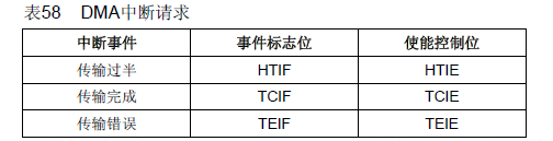
Each channel has three event flags (DMA half transfer, DMA transfer complete, and DMA transfer error), which logically OR into a single interrupt request;
Transfers between memory and memory, peripherals and memory, and memory and peripherals;
Flash memory, SRAM, peripheral SRAM, APB1, APB2, and AHB peripherals can all serve as sources and targets for access;
Programmable number of data transfers: up to 65535.
Are there enough DMA resources for STM32?
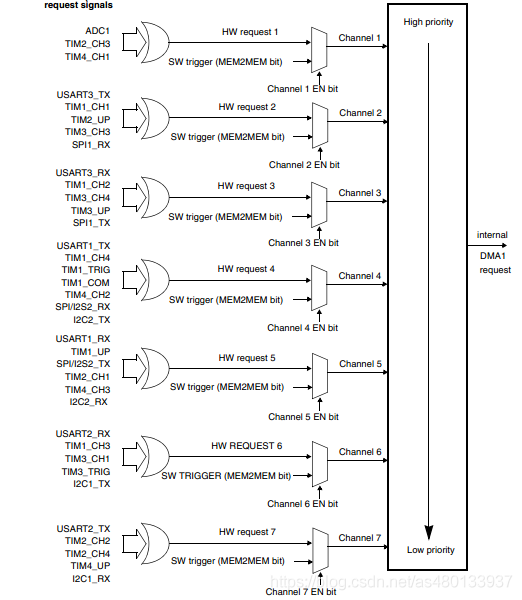
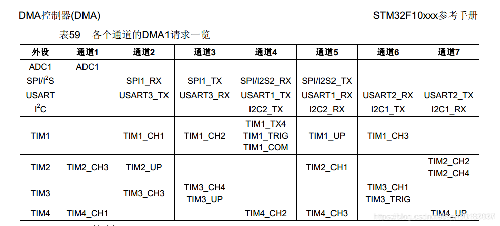
The large-capacity STM32 chips have 2 DMA controllers: DMA1 has 7 channels, and DMA2 has 5 channels. Each channel can be configured to some peripheral addresses.① DMA1 Controller7 DMA requests generated from peripherals (TIMx[x=1,2,3,4], ADC1, SPI1, SPI/I2S2, I2Cx[x=1,2], and USARTx[x=1,2,3]) are logically ORed into the DMA1 controller, with each channel corresponding to a specific peripheral:
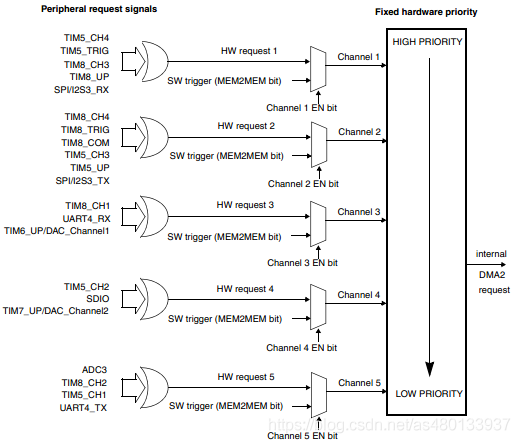
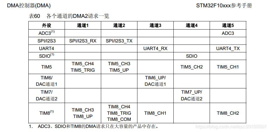
② DMA2 Controller5 requests generated from peripherals (TIMx[5,6,7,8], ADC3, SPI/I2S3, UART4, DAC channel 1, 2, and SDIO) are logically ORed into the DMA2 controller, with each channel corresponding to a specific peripheral:
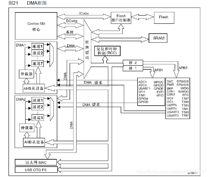
This can also be clearly seen in the system block diagram below
DMA Working System Block Diagram
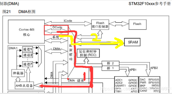
In the diagram above, we can see the connection between the STM32 core, memory, peripherals, and DMA. These hardware components are ultimately connected to the bus matrix through various lines, and data transfers between hardware structures are coordinated through the bus matrix, allowing various peripherals to harmoniously use the bus for data transmission. Let’s analyze this step by step:Next, let’s look at how data collected by the ADC is stored in SRAM with and without DMA.Without DMA1. If there is no DMA, the CPU transfers data through the core as an intermediary. For example, to transfer data collected by the ADC to SRAM, the process is as follows:The core coordinates through the DCode, accessing the data collected by the ADC stored in AHB peripherals,then the core coordinates through the DCode again to store the data into SRAM memory.With DMA TransferWith DMA,
During DMA transfer, the peripheral sends a request to the DMA controller.
The DMA controller receives the request and triggers DMA operation.
The DMA controller retrieves the data collected by the ADC from the AHB peripheral and stores it in the DMA channel.
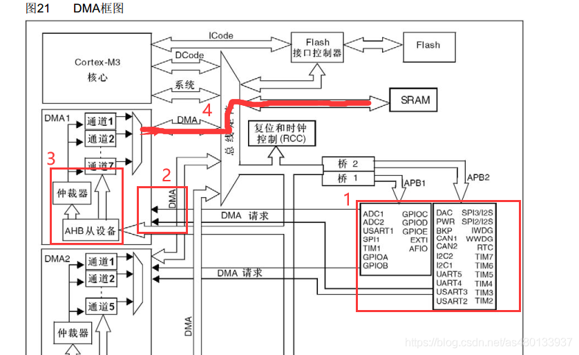
The DMA controller’s DMA bus coordinates with the bus matrix, using AHB to store the data collected by the ADC into SRAM via the DMA channel. During this data transfer process, there is no need for the core’s involvement, meaning no CPU involvement is required.
Insert image description hereWe will introduce the above steps in a more professional manner:After an event occurs, the peripheral sends a request signal to the DMA controller. The DMA controller processes the request based on channel priority. When the DMA controller begins to access the peripheral that issued the request, it immediately sends an acknowledgment signal. When the peripheral receives the acknowledgment signal from the DMA controller, it immediately releases its request. Once the peripheral releases this request, the DMA controller also withdraws the acknowledgment signal. DMA transfer ends, and if there are more requests, the peripheral can initiate the next cycle.In summary, each DMA transfer consists of three operations:
Retrieve data from the peripheral data register or from the memory address indicated by the current peripheral/memory address register. The starting address during the first transfer is specified by the DMA_CPARx or DMA_CMARx register, which indicates the base address of the peripheral or memory unit;
Store data to the peripheral data register or to the memory address indicated by the current peripheral/memory address register. The starting address during the first transfer is specified by the DMA_CPARx or DMA_CMARx register, which indicates the base address of the peripheral or memory unit;
Execute a decrement operation on the DMA_CNDTRx register, which contains the number of unfinished operations.
DMA Transfer Modes
Method 1: DMA_Mode_Normal, Normal Mode,When one DMA data transfer is completed, the DMA transfer stops, meaning it only transfers once. Method 2: DMA_Mode_Circular, Circular Transfer ModeWhen the transfer ends, the hardware automatically reloads the transfer data count register for the next round of data transfer. This means it is a multi-transfer mode.
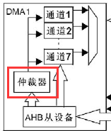
Arbitrator
The role of the arbitrator is to determine the priority of each DMA transfer.The arbitrator starts access to peripherals/memory based on the request priority of each channel.Priority management is divided into two stages:Software: The priority of each channel can be set in the DMA_CCRx register, with 4 levels:
Highest Priority
High Priority
Medium Priority
Low Priority;
Hardware: If two requests have the same software priority, the channel with the lower number has a higher priority than the channel with the higher number. For example: if software priorities are the same, channel 2 takes precedence over channel 4.Note: In high-capacity products and interconnected products, the DMA1 controller has a higher priority than the DMA2 controller.
DMA Data Flow (Only Exists on STM32F4/M4 Cores)
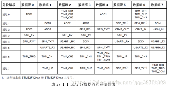
After setting up the DMA channel, you must also select the data flow corresponding to the peripheral for the channel.8 DMA controller data flows can provide a unidirectional transfer link between the source and target. Each data flow can execute:● General type transactions: transfers between memory and peripheral, peripheral to memory, or memory to memory.● Double buffer type transactions: using two memory pointers for double buffer transfers (when DMA is performing read/write operations to/from the buffer, the application can perform write/read operations to/from other buffers). The amount of data to be transferred (up to 65535) can be programmed and is related to the source width of the peripheral connected to the AHB port. After each transaction is completed, the register containing the total amount of data items to be transferred will decrement.The DMA_SxCR register controls which channel the data flow uses, and each data flow has 8 channels to choose from, with only one channel selected for DMA transfer at a time. Next, let’s look at the mapping table of each data flow channel for DMA2, as shown in Table 28.1.1:
DMA Transfer Channels
Each channel can perform DMA transfers between peripheral registers and memory addresses with fixed addresses. The amount of data transferred by the DMA is programmable, with a maximum of 65535. The register containing the number of data items to be transferred decrements after each transfer.Programmable data amount: The amount of data transferred between peripherals and memory can be programmed through the PSIZE and MSIZE bits in the DMA_CCRx register.
Pointer Increment Mode
According to the status of the PINC and MINC bits in the DMA_SxCR register, the peripheral and memory pointers can automatically increment or remain constant after each transfer. When set to increment mode, the next address to be transferred will be the previous address plus the increment value.Disabling increment mode is very useful when accessing peripheral sources or target data through a single register.If increment mode is enabled, the next transfer address will increment by 1 data width, 2 data widths, or 4 data widths based on the data width programmed in the PSIZE or MSIZE bits in the DMA_SxCR register.
Memory to Memory Mode
The operation of the DMA channel can be performed without peripheral requests; this operation is known as memory to memory mode.When the MEM2MEM bit in the DMA_CCRx register is set, the DMA transfer will start immediately when the EN bit in the DMA_CCRx register is set by software. When the DMA_CNDTRx register becomes 0, the DMA transfer ends. Memory to memory mode cannot be used simultaneously with circular mode.Note that only the peripheral interfaces of DMA2 can access memory, so only the DMA2 controller supports memory to memory transfers; DMA1 does not support it.Memory to memory mode cannot be used simultaneously with circular mode.
DMA Interrupts
Each DMA channel can generate interrupts during half transfer, transfer completion, and transfer errors. For flexibility in applications, these interrupts can be enabled by setting different bits in the registers.
If not enabled, we can also query these bits to obtain the current status of the DMA transfer. The commonly used bit is the TCIFx bit, which indicates whether the DMA transfer for data stream x is complete.Programmable data transfer widths, alignment, and data size endianness. When PSIZE and MSIZE are not the same, the DMA module aligns data according to the following diagram.Note: In high-capacity products, the interrupts for DMA2 channel 4 and DMA2 channel 5 are mapped to the same interrupt vector. In interconnected products, the interrupts for DMA2 channel 4 and DMA2 channel 5 have independent interrupt vectors. All other DMA channels have their own interrupt vectors.
DMA Memory Usage
In STM32 controllers, the chip adopts the Cortex-MX architecture, and the bus structure has been significantly optimized. DMA occupies a separate address bus, which does not conflict with the CPU’s system bus. This means that the use of DMA does not affect the CPU’s operating speed.However, note that the DMA controller and Cortex-M3 core share the system data bus for direct memory data transfers. When both the CPU and DMA access the same target (RAM or peripherals), DMA requests may halt CPU access to the system bus for several cycles. The bus arbiter performs round-robin scheduling to ensure that the CPU can obtain at least half of the system bus (memory or peripheral) bandwidth.
DMA Configuration Section
This section will introduce DMA registers and DMA library functions separately:
DMA Registers
DMA configuration parameters include: channel address, priority, data transfer direction, memory/peripheral data width, whether memory/peripheral addresses are incrementing, circular mode, and data transfer amount.
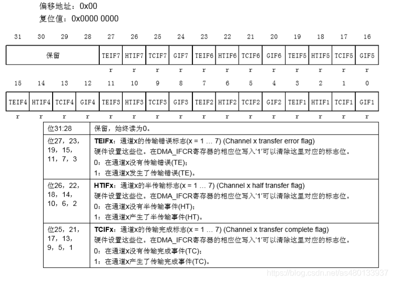
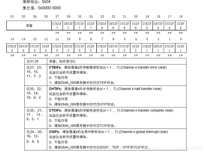
DMA Interrupt Status Register (DMA_ISR)
If we enable the interrupts in DMA_ISR, when conditions are met, it will jump to the interrupt service function. Even if not enabled, we can query these bits to obtain the current status of the DMA transfer. The commonly used bit is TCIFx, which indicates whether the channel DMA transfer is complete.Note that this register is a read-only register, so once these bits are set, they can only be cleared through other operations.
DMA Interrupt Flag Clear Register (DMA_IFCR)
The bits in DMA_IFCR are used to clear the corresponding bits in DMA_ISR by writing 0 to clear. After DMA_ISR is set, we must write 0 to the corresponding bits in this register to clear them.
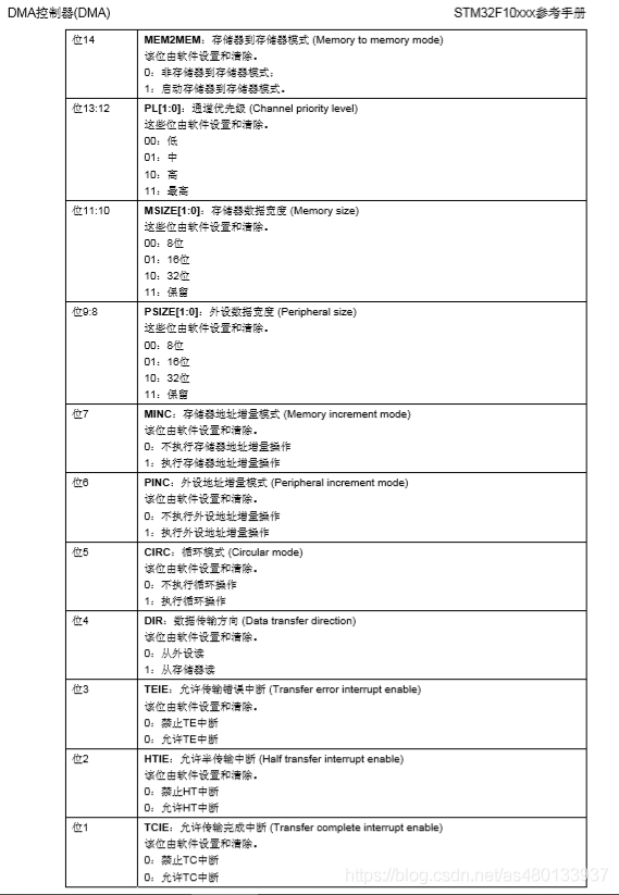
DMA Channel x Configuration Register (DMA_CCRx)
This register controls many aspects related to DMA, including data width, peripheral and memory width, channel priority, increment mode, transfer direction, interrupt enable, and enablement. Thus, DMA_CCRx is the core control register for DMA transfers.
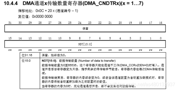
DMA Channel x Transfer Count Register (DMA_CNDTRx) (x = 1…7)
This register controls the amount of data to be transferred for each DMA channel x transfer. Its setting range is 0~65535. The value of this register decreases as the transfer proceeds. When the value of this register is 0, it indicates that the data transfer has been completed. Therefore, the value of this register can be used to know the current progress of the DMA transfer.
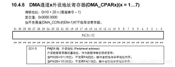
DMA Channel x Peripheral Address Register (DMA_CPARx) (x = 1…7)
This register is used to store the address of STM32 peripherals. For example, if we use UART1, this register must write 0x40013804 (which is &USART1_DR). If using other peripherals, just change to the corresponding peripheral address.
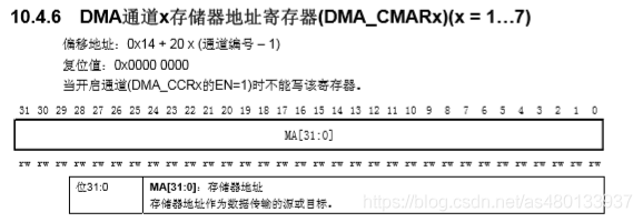
DMA Channel x Memory Address Register (DMA_CMARx)
This register is similar to DMA_CPARx but is used to hold the address of the memory. For instance, if we use the SendBuf[5200] array as memory, we would write &SendBuff in DMA_CMARx.
DMA Register Configuration Process
The channel configuration process is as follows for configuring DMA channel x (x represents the channel number):
Set the peripheral register address in the DMA_CPARx register. When a peripheral data transfer request occurs, this address will be the source or target of the data transfer.
Set the data storage address in the DMA_CMARx register. When a peripheral data transfer request occurs, the transferred data will be read from or written to this address.
Set the amount of data to be transferred in the DMA_CNDTRx register. This value decrements after each data transfer.
Set the channel priority in the PL[1:0] bits of the DMA_CCRx register.
Set the transfer direction, circular mode, peripheral and memory increment modes, peripheral and memory data widths, and whether to generate interrupts on half transfer or transfer completion in the DMA_CCRx register.
Set the ENABLE bit in the DMA_CCRx register to activate the channel.
Once the DMA channel is activated, it can respond to DMA requests from peripherals connected to that channel. After half of the data is transferred, the half-transfer flag (HTIF) is set to 1, and if the half-transfer interrupt enable bit (HTIE) is set, an interrupt request will be generated. After the data transfer is completed, the transfer complete flag (TCIF) is set to 1, and if the transfer complete interrupt enable bit (TCIE) is set, an interrupt request will be generated.
DMA Library Functions
1. DMA Initialization Function
DMA_DeInit(DMAX_ChannelX);
Function: Initializes the DMAyChannelx registers to their default values.Note: DMA is not defined in RCC_ResetCmd, so direct manipulation of DMA registers is used.
Function: Sets the channel to be activated and several parameters, including peripheral base address, memory base address, transfer data amount, increment mode, data width, etc.See the structure code description below:
typedef struct {
 uint32_t DMA_PeripheralBaseAddr;
 /* Set DMA source address */
 uint32_t DMA_MemoryBaseAddr;
 /* Set DMA destination address */
 uint32_t DMA_DIR;
 /* Set data transfer direction, determining whether to read data from the peripheral to memory or send data from memory to the peripheral, i.e., whether the peripheral is the source or destination */
 uint32_t DMA_BufferSize;
 /* Set transfer size */
 uint32_t DMA_PeripheralInc;
 /* Set whether ReceiveBuff address increments */
 uint32_t DMA_MemoryInc;
 /* Set whether memory address increments during data transfer, needs to be enabled */
 uint32_t DMA_PeripheralDataSize;
 /* Peripheral data length is for byte transfer (8bits), half-word transfer (16bits), or word transfer (32bits) */
 uint32_t DMA_MemoryDataSize;
   /* Set memory data length */
 uint32_t DMA_Mode;
 /* Set DMA mode, normal mode/circular mode, whether to send cyclically */
 uint32_t DMA_Priority;
  /* Set DMA channel priority, with low, medium, high, and very high modes */
 uint32_t DMA_M2M;
  /* Set whether it is memory to memory mode transfer, */       } DMA_InitTypeDef;
Function: Configures the specified DMAy channel x interrupt.Note: DMA_IT_TC: transfer complete, DMA_IT_HT: half transfer, DMA_IT_TE: transfer error.For example: DMA_ITConfig(DMA1_Channel1 , DMA_IT_TC , ENABLE);4. Set CNDTRx and Read CNDTRx Functions (Channel Transfer Data Count)
Function: The former sets the transfer data count for the DMA channel (when DMA is in the off state); the latter retrieves the current remaining data count for the DMA channel (when DMA is in the on state).
DMA Library Function Configuration Process:
Enable DMA clock: RCC_AHBPeriphClockCmd();
Initialize DMA channel: DMA_Init();
// Set channel; transfer address; transfer direction; number of data to transfer; data width; transfer mode; priority; whether to enable memory to memory.
Enable peripheral DMA;
For example, to enable UART DMA transmission, call the function: USART_DMACmd();
Enable DMA channel transfer; function: DMA_Cmd();
Query DMA transfer status. Function: DMA_GetFlagStatus();
Get the current remaining data size function: DMA_GetCurrDataCounter(DMA1_Channel4);
UART DMA Transfer
DMA acts as a mover, transferring data from one location to another. For example, in UART, if data is to be received, it triggers a UART interrupt, then the CPU intervenes, reading the value from the UART input register and storing it in memory. In contrast, with DMA, after generating a UART interrupt, DMA directly participates, transferring the value from the UART input register to memory, allowing the CPU to simply check the memory value, thus improving CPU efficiency.
DMA Code Configuration
① DMA Initialization Configuration
void dma_init()
{

  DMA_InitTypeDef DMA_InitStructure;
  RCC_AHBPeriphClockCmd(RCC_AHBPeriph_DMA1,ENABLE);

  /*DMA Configuration*/

  DMA_InitStructure.DMA_PeripheralBaseAddr = USART1_DR_Base;// UART data register address
  DMA_InitStructure.DMA_MemoryBaseAddr = (uint32_t)SendBuff; // Memory address (pointer to the variable to be transferred)
  DMA_InitStructure.DMA_DIR = DMA_DIR_PeripheralDST; // Direction (from memory to peripheral)
  DMA_InitStructure.DMA_BufferSize = 500; // Size of the content to be transferred
  DMA_InitStructure.DMA_PeripheralInc = DMA_PeripheralInc_Disable; // Peripheral address does not increment
  DMA_InitStructure.DMA_MemoryInc = DMA_MemoryInc_Enable; // Memory address increments
  DMA_InitStructure.DMA_PeripheralDataSize = DMA_PeripheralDataSize_Byte ; // Peripheral data unit
  DMA_InitStructure.DMA_MemoryDataSize = DMA_MemoryDataSize_Byte ; // Memory data unit
  DMA_InitStructure.DMA_Mode = DMA_Mode_Normal ; // DMA mode: one-time transfer, circular
  DMA_InitStructure.DMA_Priority = DMA_Priority_Medium ; // Priority: high
  DMA_InitStructure.DMA_M2M = DMA_M2M_Disable; // Disable memory to memory transfer

  DMA_Init(DMA1_Channel4, &DMA_InitStructure); // Configure DMA1 channel 4
  DMA_Cmd(DMA1_Channel4,ENABLE);
  DMA_SetCurrDataCounter(DMA_CH4,DMA1_MEM_LEN);// Size of DMA channel's DMA buffer
  DMA_ITConfig(DMA1_Channel4,DMA_IT_TC,ENABLE);// Configure DMA to generate interrupt after sending completion

}
#define SEND_BUF_SIZE 500 // Length of data to send, ideally a multiple of sizeof(TEXT_TO_SEND)+2.

u8 SendBuff[SEND_BUF_SIZE]; // Send data buffer
const u8 TEXT_TO_SEND[] = {"STM32F1 DMA UART Experiment"};
uint16_t i;
int main(void)
{
uart_init(115200);   // Initialize UART to 115200

 for(i=0;i<500;i++)
 {
 SendBuff[i] = 0xaf;
 }
 USART_DMACmd(USART1,USART_DMAReq_Tx,ENABLE);  // Enable UART DMA transmission

 while(1);
}
If you are over 18 and find learning [C language] too difficult? Want to try another programming language? I recommend you learn Python, currently, a 499 yuan Python beginner course is available for free for a limited time, with only 10 spots!


▲ Scan the QR code - Get it for free
Click to read the original text for more information