
LCD TVs and CRT TVs have similar basic principles in their circuit components. However, some repair technicians are unfamiliar with the logic boards of LCD TVs, and their maintenance theories and ideas have not been updated. When faced with faulty LCD TVs, they hesitate to repair them and miss out on lucrative opportunities. In fact, aside from issues with the LVDS program of the LCD screen, other faults on the logic board are generally easier to repair. Therefore, in response to the confusion expressed by forum users regarding logic board issues, I aim to simplify the content and share the maintenance approach for LCD TV logic boards in an easy-to-understand manner on the forum for everyone to benefit.
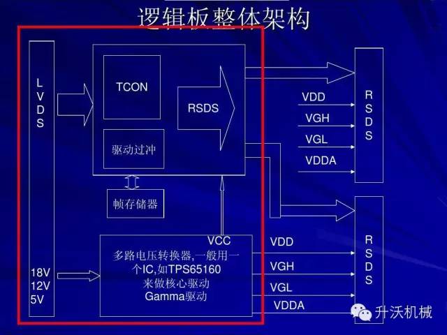
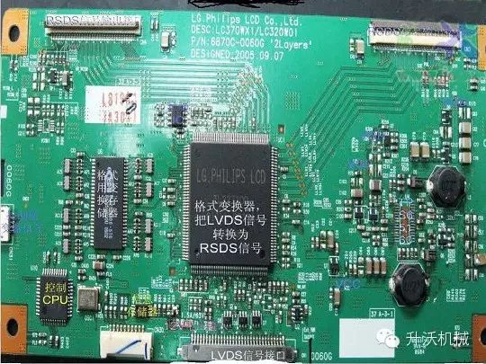
The logic board is provided by the screen manufacturer and is also known as the screen driver board, central control board, or TCON board. Its role is to process the LVDS input signals sent from the digital board (which includes three main types of signals: RGB data signals, clock signals, and control signals). After processing by the logic board, the LVDS signal converts the TTL level RGB data signals input in parallel into LVDS signals that can drive the LCD screen, which are then sent directly to the LVDS receiver chip on the LCD panel side to display images.
When inspecting the logic board, we can test the voltage to the screen, which is either 5V or 12V depending on the screen model. We then test the voltage at the LVDS output interface to see if it changes under static and dynamic conditions. If there is no change, it can generally be concluded that a fault has occurred on the logic board (during measurement, a pointer multimeter should be used to observe slight fluctuations, typically around 1.2V). If possible, substituting it with an identical logic board is the most reliable method, as long as the format and screen voltage are the same, to help us identify the fault point.
The LVDS lines from the main board to the logic board follow a certain pattern; the red wire is usually the positive power line, the black wire is generally the negative power line, and the twisted wires are the LVDS signal lines (4 pairs – single 6-pin; 5 pairs – single 8-pin; 8 pairs – dual 6-pin; 10 pairs – dual 8-pin). Currently, some logic boards are integrated with the screen, referred to as X+C integrated types, generally for screens below 32 inches, while screens above 32 inches are typically composed of separate X+C configurations (the smaller screens are mainly due to cost considerations). Due to technical and precision characteristics, they are generally difficult to repair. However, if the principles are well understood and the soldering skills are strong, repairing the logic board is not a myth!
The damage to the logic board can cause the screen to fail to display images normally, and there will naturally be no menu display, although the buttons and remote control will still function (keep this in mind). If the screen has intermittent colored lines vertically, there will be no characters displayed (this point is also very important).
If the connection line between the logic board and screen is poor, the screen will display many small colored dots mixed in the image. You can confirm this by unplugging and plugging the line back in; the logic board and screen can both cause image distortion, but the distortion from the logic board is different from that of the screen. The distortion from the logic board presents as a regular pattern vertically. We can change the signal source or switch to a 4:3 mode to confirm. Below are quick methods to determine if there is a fault in the LCD TV logic board circuit: (1) Check whether the input video signal waveform sent from the digital image processing circuit on the logic board is normal. If there is a normal waveform input, it indicates that the preceding digital image processing circuit is functioning correctly. (2) Check whether the voltage input from the power supply to the logic board is normal. If the input voltage is normal, it indicates that the power supply circuit is working properly. (3) Check whether the LCD screen driving signal waveform output from the screen line interface on the logic board is normal. If there is no normal waveform output, it may indicate a fault in the logic board circuit. Below are common fault phenomena and maintenance approaches: Fault Phenomenon 1: No image. Analysis and repair: This type of fault is mostly caused by the logic board lacking power voltage. Due to differences in the manufacturing process of screens, generally, screens 26 inches and larger will display a black screen when the logic board lacks power voltage, while the backlight may be on, sometimes appearing as a gray screen; screens smaller than 26 inches typically present as a white screen. During actual repair, the first step is to check whether the power voltage to the logic board is normal. If the voltage is normal, it indicates that the power supply circuit on the signal board is functioning correctly, at which point check whether the fuse on the logic board is blown. If the fuse is blown, and after confirming that there is no short circuit in the subsequent stage, you can try replacing the fuse resistor. If there is no voltage or the voltage is low, unplug the screen line connector from the logic board and measure whether the voltage sent from the signal board to the screen is normal. If normal, it indicates that there is a short circuit fault on the logic board; otherwise, the problem lies with the signal board. Fault Phenomenon 2: There is an image, but the color or contrast is abnormal. Analysis and repair: Measure whether the data signal at the logic board is normal; if conditions allow, use an oscilloscope for measurement. Since the actual measured waveform may not be very clear, to determine this, you can unplug the closed line, that is, when there is no signal input, measure its waveform again to judge whether there is data signal by comparison. If you do not have an oscilloscope, you can use the method of measuring DC voltage for a rough judgment. After powering on for a few minutes, touch the surface temperature of the integrated circuits on the logic board; under normal conditions, it should feel slightly warm. If the temperature rises too quickly, it generally indicates a fault in that circuit. Typically, the fault phenomena caused by logic board damage are as follows: images lack levels, detail, or appear as negatives; moving images may have trailing effects or poor clarity; images may appear embossed with stiff lines; or localized areas of the image may show color spots or blocks. Fault Phenomenon 3: Vertical stripes appear on the screen. Analysis and repair: This fault can be divided into two categories: one is full-screen colored vertical stripes; the other is vertical stripes in the upper area of the image. Since this type of fault is very similar to the fault phenomena caused by LCD screen damage, it is generally advisable to replace it with a logic board of the same model to accurately determine the fault location. If the fault persists after replacing the logic board, it indicates that there is an issue with the LCD screen; otherwise, it indicates that the original logic board is faulty. Repair example: 1: Model: TLM4236P Chip: LCD-MST6 Fault Phenomenon: Sound but no image, black screen. Analysis and repair: Upon powering on, check the backlight; the screen power supply of 12V is normal. The remote control power on/off is functioning normally, indicating that the main board control section is working correctly, thus focusing on checking the logic board.
The logic board mainly consists of format converter circuits and DC/DC converter circuits. Since the screen cannot light up, the DC/DC converter circuit is the key focus for inspection. For convenience in repair, let’s briefly analyze the control process of this circuit.
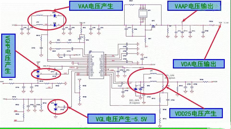
VCC-PANEL enters pins 20, 21, and 22 of UP1, and after internal conversion within the chip, outputs 2.5V voltage from pin 18 (SWB) and stabilizes it to 1.8V through UP5 to power the format conversion chip. Pin 11 (DRN) of UP1, through DP7, C227, and internal components of pin 11 of UP1, forms a boost circuit that outputs approximately -5.6V of VGL voltage to provide negative power supply for row and column driving.
When the UP1 chip detects that 2.5V is functioning normally, the boost circuit formed by LP7, LP2, DP2, DP6, and internal circuits of pins 4 (SW) and 5 (SW) of UP1 begins to operate, outputting approximately 16V voltage. Pin 27 (GD) of UP1 provides an enabling signal for QP1 and QP2; the 16V voltage passes through QP1 and QP2 to provide VDA voltage for the row and column driving circuit.
Once all the above circuits are functioning normally, VAAP goes through the boost circuit formed by DP5, CP18, and pin 10 (DRP) of UP1, starting to work normally, and through RP21 limiting current, gets VGHP voltage, which outputs approximately 22V of VGH voltage through QP8 to provide power supply for row and column driving.
From the above analysis, it can be seen that there is a strict timing relationship when this circuit starts to work normally. Therefore, check each voltage according to this timing relationship and find that the VGHP voltage is only 10.5V, while it should normally be 19.5V. The VGH voltage is 0V, while it should be 18V. Clearly, the problem arises because the VGHP voltage cannot be boosted normally.
Upon checking, the voltage at pin 10 of UP1 is 0V, whereas it should be able to detect a DC voltage of 2.25V; when checking AC, there is about 5V AC voltage, but both AC and DC voltages cannot be detected in practice. Measuring the resistance of this pin to ground shows no abnormalities, suspecting that pin 10 of UP1 is damaged internally, and replacing it resolves the fault. 2: Model: TLM40V68P Chip: LCD-MST6M68FQ Fault Phenomenon: White screen. Analysis and repair: Upon powering on, the entire machine starts normally, but the screen takes a long time to light up and then presents a white screen, while sound and other functions are normal, thus determining the fault is in the logic board.
First, check the power supply of each route on the logic board and find that the VGHP test point has no voltage, while normally this test point should have 19.5V. After measuring other test points, the voltages are normal. Remove the logic board and measure the resistance of the VGHP output terminal to ground, which is 0 ohms. Clearly, this issue is due to the absence of VGHP voltage. When the filter capacitor CP19 is removed, the resistance of the VGHP output terminal to ground returns to normal. Reinstall the logic board, power on, and the fault persists. Measuring again shows no VGHP voltage. Further measuring pin 10 of UP1 shows normal DC 2.25V and AC 5V output, and the VAA test point also has normal 13V voltage. Thus, it is determined that the absence of VGHP voltage is due to an open circuit in DP5, and after direct replacement, VGHP voltage outputs a normal 19.5V, restoring the entire machine to normal.
The analysis of this fault formation indicates that the VGHP voltage is a high potential provided for the gate level, which means it is the voltage that opens the gate level. When the LCD screen loses this voltage, it causes the LCD TFT inside to fail to operate normally, leading to this type of fault. 3: Flower screen (with general significance)
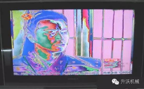
Generally, the user menu is normal, but the image exhibits a flower screen phenomenon. The issue is usually in the computer board and scaler processing chip circuit. This situation can be judged by re-soldering; by pressing the chip, observe whether there are significant changes in the flower screen phenomenon. If there are notable changes, it is caused by poor soldering of this chip. Use special tools, such as a hot air gun, to heat the IC and re-solder the poorly contacting pins.
If the screen exhibits a flower screen and intermittent flower screen faults, it is commonly due to poor contact of the LVDS connection wires. Cleaning the connection wires can resolve this. If the TV’s flower screen changes after repeated power on, with variations in stripes and colors, then it is generally a fault in the driver board, and replacing the driver board will suffice. If the flower screen shows no changes in stripes and colors after repeated power on, then the screen itself is faulty, and the driver board must also be replaced to test the screen. One factor not to be overlooked regarding the flower screen is the screen parameter error.
The screen parameter refers to the data signal sent from the main board to the screen logic board. Specifically, it means that the main board produced by the manufacturer can be matched with various models of LCD screens, but corresponding adjustments need to be made in the bus, similar to how adjustments are made for dark balance and other calibrations when replacing a CRT tube. Different screens have different signal data.
When images and characters appear on the screen (which is a significant distinction from logic board faults), it may indicate a screen parameter error. At this point, you can enter the bus to adjust the screen parameters.
Taking Changhong LCD TVs as an example, generally, the way to enter the bus is: in TV mode, lower the volume to 0, press and hold the mute button on the remote for 3 seconds, and then press the menu button on the machine to enter the factory mode menu. Adjustment methods and data: The number behind the index represents the current adjustment index number, and you can switch to different index numbers on this page by pressing the “P+/P-” buttons. During operation, directly press the number keys or the “P+/P-” buttons to select the item to be adjusted, and press the “V+/V-” buttons to adjust the parameters of the item.
If the software version of the LCD TV is too low, the screen parameter data may easily change. Again, taking Changhong as an example, USB can be used to upgrade the machine. First, extract the software and place it in the root directory of the USB drive, insert the USB into USB1 of the machine, and after powering on the whole machine, in TV state, press the “menu” button on the remote and continuously press 6-1-6-9, after which the machine will automatically detect the USB drive and prompt whether an upgrade is needed.
If you are unable to determine the cause of the flower screen on the TV, it is recommended to seek a professional screen repair technician, as there may be differences among various brands and models of LCD TVs, and some LCD TVs may inherently have defects in the screen. Based on my own screen repair skills, as I do not have specialized equipment such as a screen press machine, combined with my limited skills, I cannot compare with expert screen repair technicians. Consequently, I have ruined numerous screens that could have been repaired, so it is advisable to handle such situations with caution.
The content of this article is sourced from the internet, and the copyright belongs to the original author. If there are any issues, please contact us in a timely manner for proper handling.
Exciting articles:
Six Steps of Home Service Marketing
The Three Realms of Serving Customers, Which Level Have You Reached?
Service Standards: Execution Standards for On-Site Services
Home appliance service engineers should say these three sentences when facing complaints!
What Would You Do If a Home Appliance Repair Technician Was Late in Providing Service?
For related cooperation, please add WeChat ID:caiman39
Welcome to submit articles and discuss the development of the home appliance service industry together!
Likes are a form of encouragement; sharing conveys friendship.

Clicking on advertisements is also a reward for the editor!