This article explains the voltage matching issues of regenerative feedback servo drives using Siemens’ SIMODRIVE611 series drives as an example. The SIMODRIVE611 was once one of Siemens’ main servo drive products, widely used in systems such as SINUMERIK840D/810D/802D/840C, and is specifically divided into 611D (digital), 611U (digital-analog hybrid), and 611A (analog) types. Compared to traditional servo drive products, an important feature of the 611 servo drive is its use of a regenerative feedback power type for medium and large power servos.
1. Regenerative Feedback Power Supply
The power module of the SIMODRIVE611 is divided into non-feedback modules (U/I Module) and regenerative feedback modules (I/R Module). For small power supplies, the SIMODRIVE611 uses non-feedback power modules, while for medium and large power, it uses regenerative feedback power modules, with rated powers including: 16KW, 36KW, 55KW, 80KW, and 120KW. The regenerative feedback module regenerates all the braking energy from the servo motor into current and feeds it back into the workshop power grid. In other words, when the motor is running, the drive draws electrical energy from the workshop power grid, and when the motor brakes, it enters a generating state, sending electrical energy back into the workshop power grid.
The non-feedback module converts the motor’s braking energy into thermal energy consumed by built-in or external braking resistors.
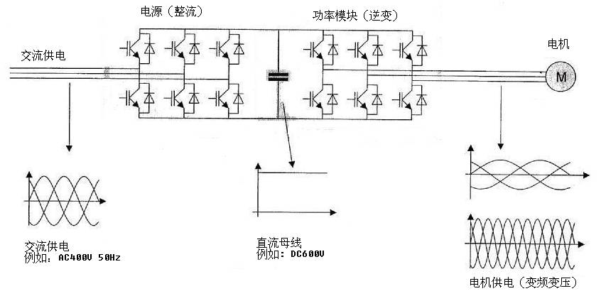 Energy exchange in the drive is reversible.
Regenerative feedback drives are suitable for frequent starts and stops, frequent braking, and situations with large braking inertia for medium and large power. They are particularly suitable for machines with characteristics such as metal cutting. Due to the advanced Power Factor Correction (PFC) circuit used in the internal feedback power supply module of the SIMODRIVE611, the rectified power factor is nearly 1, and the harmonic impact on the power grid is minimal (THD<3%). The use of IGBT as a reversible power device makes it more energy-efficient overall. The higher the machine speed, the greater the motion inertia, the more axes, and the more frequent the braking, the more pronounced the energy-saving effect becomes. This advantage has significant practical significance in today’s era that emphasizes energy conservation and environmental protection. Currently, the trend indicates that regenerative energy feedback is the mainstream direction for servo drive development. For example, the CRH Harmony high-speed trains and urban subway vehicles in China all use regenerative feedback braking.
2. Feedback Current of Regenerative Feedback Power Supply
The regenerative feedback current can be in the form of a sine wave or a square wave, depending on the setting of the DIP switch at the top left corner of the power module and whether a Siemens standard filter is installed. If the default setting of the DIP switch is used (S1.3=OFF, S1.6=ON), and a Siemens standard sine wave filter is installed after the main line switch, the regenerative feedback current will be a sine wave current, consistent with the current waveform in the AC power supply grid. If the Siemens standard sine wave filter is not used, the feedback current will be a square wave current, and S1.6 should be set to OFF.
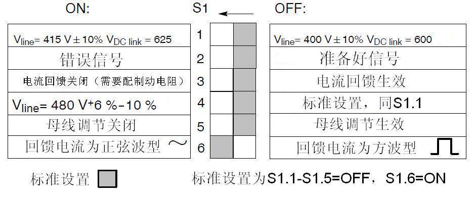
Meaning and standard settings of the DIP switch.
The current fed back to the grid is generally generated during the machining program execution of the machine tool. For example, when executing the M05 command, the spindle motor rapidly decelerates from a high-speed rotation state to 0, resulting in a large feedback current. There will also be feedback current when each feed axis stops. Overall, as long as the drive remains in an enabled state, feedback current will continuously be generated. However, if the pulse enable is removed and the motor is in a free stop state, no feedback current will be generated.
3. Voltage Matching of Regenerative Feedback Power Supply
For regenerative feedback servo drives, appropriate voltage matching (Voltage matching) is very important. For users, voltage matching mainly involves selecting the appropriate workshop transformer or equipment transformer.
Due to the continuous feedback current being sent into the grid, it is equivalent to having many small generators in the grid, and the larger the external grid capacity, the better. Specifically, if each workshop uses a distribution transformer to connect to the factory grid for power supply, the ratio of the short-circuit power SK line of the workshop transformer to the rated power Pn of the power module should meet:
SK line /Pn≥ 60…100
For example, if a workshop only installs 3 SIMODRIVE611 regenerative feedback servo drive machine tools, each with a rated power of 36KW, the short-circuit power of the workshop distribution transformer should be greater than 6480KW. In practice, it is more common for the workshop to have both standard equipment and CNC equipment equipped with regenerative feedback servo drives. In this case, the total capacity should be considered first, and then the total rated power of the regenerative feedback servo should be verified according to the above formula. If it is insufficient, consider increasing the transformer capacity. Generally, the number of various types of equipment in a workshop is large, and the capacity of the distribution transformer will be relatively large (unless there is a clearly undersized situation), which should basically meet the above requirements.
There is also a situation where a transformer is installed separately for a machine tool equipped with a SIMODRIVE611 feedback drive. In this case, the capacity of this transformer must be verified separately. In addition to meeting the capacity requirements of other loads (such as hydraulic pump stations, chip removers, electrical cabinet air conditioning, etc.) of the machine tool, the rated power Sn of the transformer should at least meet:
Sn1 ≥ 1.27 Pn
And should also meet:
Sn2=SK transformer[KVA] x Uk [%] /100 [%] [KVA]
If the two values are different, the larger power capacity should be chosen. For example, if the rated power of the feedback drive power module is 16KW, and the short-circuit impedance Uk of the transformer is 3%, with a short-circuit power of 830KVA, then:
Sn1=1.27×16=20.32KW
Sn2=830×3/100=24.9KVA
Since Sn2>Sn1, take Sn2, and the rated power of the transformer should be greater than 24.9 KW (not considering other load requirements of the equipment). In practice, considering the other loads of the equipment, the rated power of the transformer should be increased accordingly.
4. Short-Circuit Impedance of the Transformer
From the above example, it can be seen that the Uk (short-circuit impedance, also known as “impedance voltage” or “short-circuit voltage”) of the transformer is a very important parameter, and its value directly determines the rated capacity of the transformer to be selected. When the short-circuit impedance is small, the matching transformer capacity can be small, while when the short-circuit impedance is large, the matching transformer capacity should be increased. This is an indicator that people often overlook.
If the capacity of the workshop transformer is sufficiently large, this issue can generally be ignored. However, if a transformer is equipped separately for one or several CNC machine tools with feedback drives, this issue must be considered separately.
Generally, when selecting a transformer, people only consider the power indicators of the transformer, while the short-circuit impedance is often overlooked. A smaller short-circuit impedance means that the terminal voltage fluctuates less with load, resulting in a smaller voltage drop, making it easier to control and ensure voltage quality. The short-circuit impedance of a transformer basically reflects its inductive reactance. A larger short-circuit impedance indicates a greater inductive reactance, which hinders the ability to change current. For regenerative feedback power modules, when the feedback current is sent back into the grid, the primary coil of the transformer becomes the secondary coil. A smaller short-circuit impedance allows the feedback current to enter the grid more smoothly, while also resulting in smaller voltage fluctuations. Conversely, if the short-circuit impedance of the transformer is too large, it will hinder the feedback current from entering the grid, indirectly affecting the internal inverter components of the drive, and in severe cases, even causing DC bus over-voltage alarms.
For transformers directly connected to feedback drives, the short-circuit impedance is generally required to be: Uk ≤3%
Some users use voltage stabilizers before the CNC machine tool’s electrical cabinet. If a self-coupling transformer-based voltage stabilizer is used (which is the most common type), it is treated as if a transformer has been installed before the incoming line. In this case, the same short-circuit impedance requirements should apply; otherwise, it may not only fail to have a positive effect but may also cause issues. This situation has been verified multiple times: when using a voltage stabilizer, occasional DC bus over-voltage alarms occur, while bypassing the stabilizer (selecting “pass through city electricity”) has no issues at all.
Within the allowed voltage fluctuation range, the DC bus voltage output by the regenerative feedback module is stable, and there is no need to install a voltage stabilizer for this. However, if there are other loads in the equipment that are sensitive to voltage fluctuations, and a voltage stabilizer must be used, its capacity should be matched according to the actual short-circuit impedance. If the impedance is high, the capacity of the voltage stabilizer should be increased accordingly compared to when the impedance is low.
5. Other Usage Considerations
To better use the SIMODRIVE611 regenerative feedback servo drive, several other points need to be noted:
(1) The SIMODRIVE611 drive is designed to be directly connected to the TN power grid, whether it is a three-phase four-wire or three-phase five-wire system, which means that the PEN or PE line in the power grid must be used directly. If a separate ground wire is made for a specific device, this ground wire can be used for repeated grounding but cannot replace the PEN or PE line in the workshop distribution system. If only this single ground wire is used without the PEN/PE line in the distribution system, it becomes a TT power grid, and an isolation transformer must be added before the incoming line.
(2) Using appropriate pulse resistor modules in the drive group can absorb the energy from the DC bus in a timely manner during sudden power outages in the workshop or faults during feedback processes, suppressing the rise of the DC bus voltage and better protecting the drive group. In this regard, pulse resistor modules are more beneficial for feedback drives than voltage stabilizers, and they are much cheaper.
(3) Before turning off the main power supply, ensure that terminal 48 of the power module is in a disabled state (i.e., the DC bus is not in a charging state). Intuitively, this means that before turning off the main power supply, the yellow LED indicating the charging state of the DC bus on the power module should be off.
(4) All connection screws on the DC bus should be M4 screws, and the connection of each screw should be kept tight. The standard torque is 1.8Nm (tolerance 0—+30%), and regular checks of the tightness should be performed. Loose screws can cause arcing and overcurrent, posing significant hazards to the drive group.
(5) Generally, a Siemens line filter should be used before the reactor. Line filters have a good filtering effect on higher harmonics, and the impact of higher harmonics on control system components is much greater than that of general voltage fluctuations.
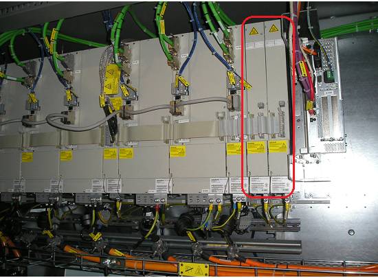 The two modules on the far right of the drive group are the pulse resistor modules.
This article is published with the author’s consent and was originally published in “Machine Tool Electrical Equipment”.
Thank you for your attention! WeChat ID: Siemens_CNC_TAC
Scan to follow:


↓↓↓↓↓↓Click to read the original text for historical information