unsetunset1. Introductionunsetunset
1. Learning Objectives
The goal of this article is to guide you through the use of the DS1302 real-time clock module to display the current time in real-time on an OLED display. We will help you gain a comprehensive understanding of the DS1302 module by introducing hardware connections, basic module configurations, and program writing.
2. Module Application Background
The DS1302 real-time clock module is widely used in embedded systems, with its core advantage being the provision of a standalone, accurate, and continuous time reference. Here are some common application scenarios:
- Data logging and timestamping
- Timed automation control
- Electronic clock and calendar display
- System event scheduling and log management
- Time management in low-power devices
unsetunset2. Module Overviewunsetunset
1. Physical Display
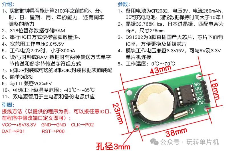
The DS1302 real-time clock module consists of the following main components:
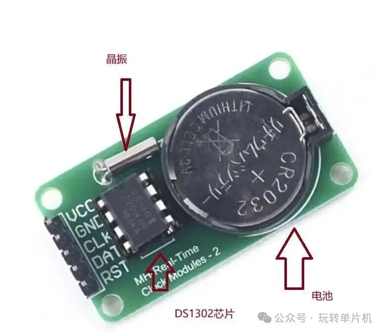
- Battery: Used to keep the clock running even when the system is powered off, ensuring the clock continues to operate.
- Crystal Oscillator: Provides clock signals to the chip, ensuring time accuracy.
- DS1302 Chip: The core part of the module, responsible for generating and managing the clock and date.
This module can be found in various electronic projects, especially in scenarios where time display or date recording is required.
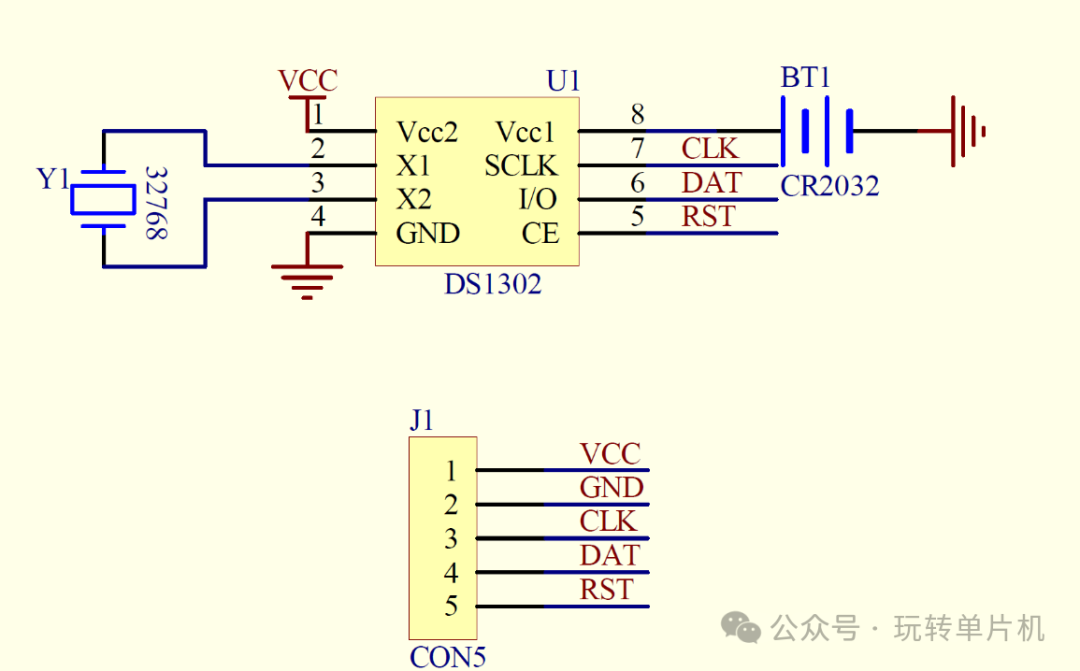
2. Module Schematic
The pins and functions of the DS1302 module are as follows:
- Vcc1: Backup power supply, providing continuous power to the clock to prevent power loss.
- Vcc2: Main power pin, usually connected to a 3.3V or 5V power supply.
- X1 and X2: Connect the crystal oscillator to provide a stable clock signal to the chip.
- CE: Enable pin, controlling the start and end of data transmission.
- I/O: Bidirectional data input/output pin for transmitting commands and data.
- SCLK: Serial clock pin, providing a synchronous clock signal from the master control unit.
Working Principle: Read/Write Timing
The DS1302 communicates with the microcontroller via a three-wire serial interface. The microcontroller sets the RST pin to high to enable the DS1302, then provides a serial clock signal through the SCLK pin, and performs data read/write operations through the I/O pin. The clock and date data are stored in BCD code (binary-coded decimal) format for easy reading and display.
unsetunset3. Hardware Connectionunsetunset
1. Hardware Connection Diagram
The connection method between the DS1302 real-time clock module and the STM32 microcontroller is as follows:
| DS1302 Pin | STM32 Pin |
|---|---|
| VCC | 3.3V |
| GND | GND |
| CLK | A2 |
| DAT | A1 |
| RST | A0 |
Connection Diagram:
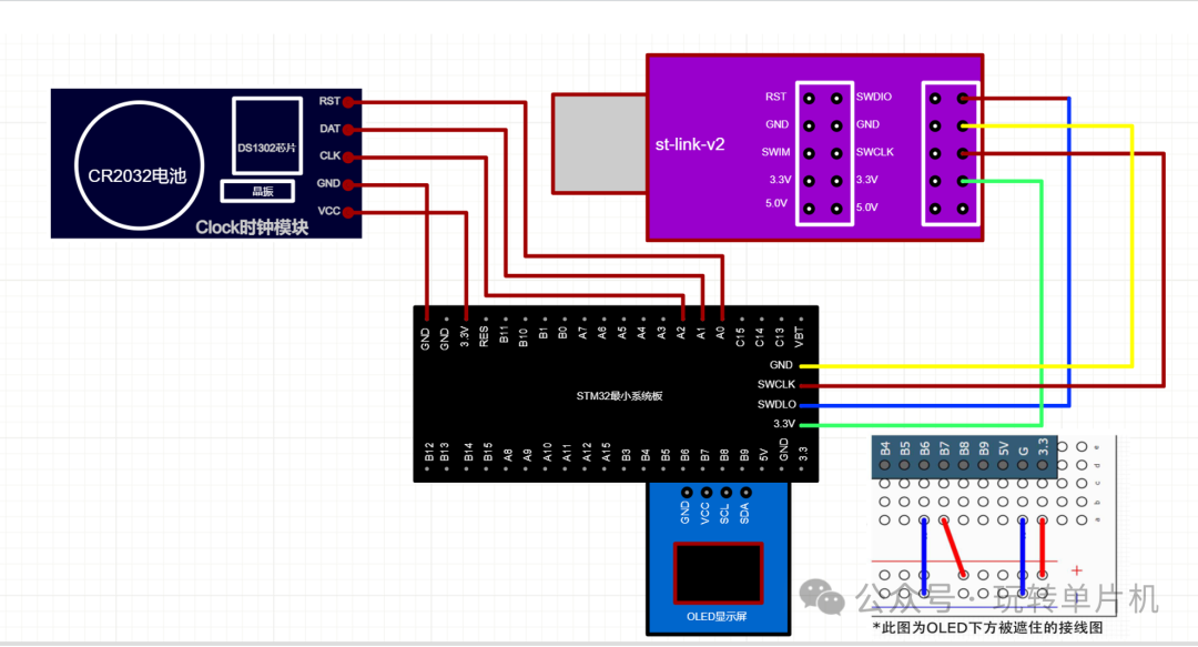
2. Hardware Connection Method
Connect the pins as follows:
- VCC pin connected to the 3.3V power supply of the STM32.
- GND pin connected to ground (GND).
- CLK pin connected to STM32’s A2 pin (for providing serial clock signal).
- DAT pin connected to STM32’s A1 pin (for data transmission).
- RST pin connected to STM32’s A0 pin (for enabling DS1302).
With these connections, we can ensure that the STM32 can communicate smoothly with the DS1302 real-time clock module.
unsetunset4. Experimental Resultsunsetunset
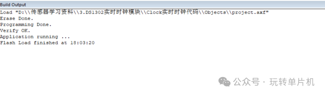
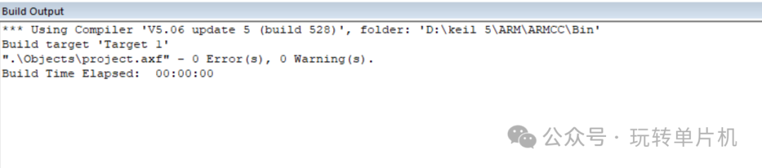
1. Operation and Programming Results
After completing the hardware connections, the next step is to write the program and upload it to the STM32. Once successfully uploaded, the program will run, and the OLED display will accurately show the current time information. Here are the display effects:
2. Video Demonstration
Here is a video demonstration showcasing the actual operation of the DS1302 real-time clock module, including how to obtain the time through the DS1302 and update the display in real-time on the OLED screen.
unsetunset5. Module Code Exampleunsetunset
To help you better understand the use of the DS1302 module, here is a simple code example demonstrating how to use the DS1302 with STM32 to obtain the current time and display it on the OLED screen.
#include "ds1302.h"// Clock module header file
#include "sys.h"
#include "delay.h"

 // Define global variables
struct TIMEData TimeData; // Global variable for time data
struct TIMERAM TimeRAM;  // Global variable for RAM data
u8 read_time[7];   // Store BCD time data read from DS1302

 // Initialize SCLK and CE pins
void DS1302_GPIO_Init(void)
{
 GPIO_InitTypeDef GPIO_InitStructure;
 RCC_APB2PeriphClockCmd(DS1302_CLK, ENABLE);// Enable GPIO clock

 // Configure SCLK pin
 GPIO_InitStructure.GPIO_Pin = DS1302_SCLK_PIN;
 GPIO_InitStructure.GPIO_Speed = GPIO_Speed_50MHz;// 50MHz output speed
 GPIO_InitStructure.GPIO_Mode = GPIO_Mode_Out_PP;// Push-pull output mode
 GPIO_Init(DS1302_SCLK_PORT, &GPIO_InitStructure);
 GPIO_ResetBits(DS1302_SCLK_PORT,DS1302_SCLK_PIN); // Initialize to low level

 // Configure CE pin
 GPIO_InitStructure.GPIO_Pin = DS1302_CE_PIN;
 GPIO_InitStructure.GPIO_Speed = GPIO_Speed_50MHz;
 GPIO_InitStructure.GPIO_Mode = GPIO_Mode_Out_PP;
 GPIO_Init(DS1302_CE_PORT, &GPIO_InitStructure);
 GPIO_ResetBits(DS1302_CE_PORT,DS1302_CE_PIN); // Initialize to low level
}

// Configure data pin as output mode for writing data to DS1302
void DS1302_DATAOUT_init()
{
 GPIO_InitTypeDef GPIO_InitStructure;
 RCC_APB2PeriphClockCmd(DS1302_CLK, ENABLE);

 GPIO_InitStructure.GPIO_Pin = DS1302_DATA_PIN;
 GPIO_InitStructure.GPIO_Speed = GPIO_Speed_50MHz;
 GPIO_InitStructure.GPIO_Mode = GPIO_Mode_Out_PP; // Configure DATA pin as push-pull output mode
 GPIO_Init(DS1302_DATA_PORT, &GPIO_InitStructure);
 GPIO_ResetBits(DS1302_DATA_PORT,DS1302_DATA_PIN);// Initialize to low level
}

// Configure data pin as input mode for reading data from DS1302
void DS1302_DATAINPUT_init()
{
 GPIO_InitTypeDef GPIO_InitStructure;
 RCC_APB2PeriphClockCmd(DS1302_CLK, ENABLE);
 GPIO_InitStructure.GPIO_Pin = DS1302_DATA_PIN;
 GPIO_InitStructure.GPIO_Mode = GPIO_Mode_IN_FLOATING;// Configure DATA pin as floating input mode
 GPIO_Init(DS1302_DATA_PORT, &GPIO_InitStructure);
}

// Write one byte of data to DS1302, sending data bit by bit in LSB (least significant bit first) order
void DS1302_write_onebyte(u8 data)
{
  u8 count=0;
  SCLK_L;// Ensure clock line is low
  DS1302_DATAOUT_init();// Configure data line as output mode

// Loop to send 8 bits of data
 for(count=0;count<8;count++)
  { SCLK_L; // Pull clock line low, prepare to send data bit
   // Set data line level according to the value of the data bit
   if(data&0x01)// Check the least significant bit
   {DATA_H;}  // Data bit is 1, pull data line high
   else{DATA_L;}
   SCLK_H;    // Pull clock line high, DS1302 samples data on the rising edge
   data>>=1;   // Right shift data, prepare to send the next bit
  }
}

// Write data to a specified register in DS1302, address is the register address, data is the data to be written, first send the address byte, then send the data byte
void DS1302_wirte_rig(u8 address,u8 data)
{
 u8 temp1=address;
 u8 temp2=data;
 // Initialize communication
 CE_L;// Chip select low
 SCLK_L; // Clock low
 delay_us(1);
 CE_H;// Chip select high, start communication
 delay_us(3);
 // Send address byte and data byte
 DS1302_write_onebyte(temp1);// Send register address
 DS1302_write_onebyte(temp2);// Send data
 // End communication
 CE_L;// Chip select low
 SCLK_L;// Clock low
 delay_us(3);
}

// Read data from a specified register in DS1302, address is the register address, first send the address byte, then read the data byte
u8 DS1302_read_rig(u8 address)
{
 u8 temp3=address;
 u8 count=0;
 u8 return_data=0x00; // Initialize return data
 // Initialize communication
 CE_L;// Chip select low
 SCLK_L;// Clock low
 delay_us(3);

 CE_H;
 delay_us(3);
 // Send the register address to read
 DS1302_write_onebyte(temp3);
 // Configure data line as input mode
 DS1302_DATAINPUT_init();
 delay_us(3);
 // Loop to read 8 bits of data
 for(count=0;count<8;count++)
  {
  delay_us(3);
  return_data>>=1;// Right shift to prepare to receive the next bit

  SCLK_H;// Pull clock line high
   delay_us(5);

  SCLK_L;// Pull clock line low, DS1302 outputs data on the falling edge
   delay_us(30);

   // Read data bit
  if(GPIO_ReadInputDataBit(DS1302_DATA_PORT,DS1302_DATA_PIN))
  {return_data=return_data|0x80;}   // Data bit is 1, set the highest bit

  }
 delay_us(2);
 CE_L;// Chip select low, end communication
  DATA_L;// Pull data line low
 return return_data;// Return the read data
}

// Initialize DS1302 chip
void DS1302_Init(void)
{
 DS1302_wirte_rig(0x8e,0x00);// Disable write protection
 DS1302_wirte_rig(0x80,0x03);// Set seconds register
 DS1302_wirte_rig(0x82,0x27); // Set minutes register
 DS1302_wirte_rig(0x84,0x17);// Set hours register
 DS1302_wirte_rig(0x86,0x17);// Set day register
 DS1302_wirte_rig(0x88,0x10);// Set month register
 DS1302_wirte_rig(0x8a,0x03); // Set week register
 DS1302_wirte_rig(0x8c,0x25);// Set year register
 DS1302_wirte_rig(0x8e,0x80);// Enable write protection
}

// Read time data from DS1302 (in BCD format)
void DS1302_read_time(void)
{
 read_time[0]=DS1302_read_rig(0x81);// Read seconds
 read_time[1]=DS1302_read_rig(0x83);// Read minutes
 read_time[2]=DS1302_read_rig(0x85);// Read hours
 read_time[3]=DS1302_read_rig(0x87);// Read day
 read_time[4]=DS1302_read_rig(0x89); // Read month
 read_time[5]=DS1302_read_rig(0x8B);// Read week
 read_time[6]=DS1302_read_rig(0x8D);// Read year
}

// Convert BCD time data to decimal and store in TimeData structure
void DS1302_read_realTime(void)
{
 DS1302_read_time(); // First read raw BCD time data
 TimeData.second=(read_time[0]>>4)*10+(read_time[0]&0x0f);// Convert seconds: BCD to decimal
 TimeData.minute=((read_time[1]>>4))*10+(read_time[1]&0x0f);// Convert minutes: BCD to decimal
 TimeData.hour=(read_time[2]>>4)*10+(read_time[2]&0x0f);// Convert hours: BCD to decimal
 TimeData.day=(read_time[3]>>4)*10+(read_time[3]&0x0f);// Convert day: BCD to decimal
 TimeData.month=(read_time[4]>>4)*10+(read_time[4]&0x0f);// Convert month: BCD to decimal
 TimeData.week=read_time[5];// Week is read directly (usually no conversion needed)
 TimeData.year=(read_time[6]>>4)*10+(read_time[6]&0x0f)+2000;// Convert year: BCD to decimal and add 2000
}

// Write user data to DS1302's RAM
void DS1302_wirteRAM(void)
{
 DS1302_wirte_rig(0x8e,0x00); // Disable write protection

 // Write data to RAM
 DS1302_wirte_rig(0xC0,TimeRAM.hour_kai);// Start time - hours
 DS1302_wirte_rig(0xC2,TimeRAM.minute_kai);// Start time - minutes
 DS1302_wirte_rig(0xC4,TimeRAM.hour_guan);// End time - hours
 DS1302_wirte_rig(0xC6,TimeRAM.minute_guan);// End time - minutes
 DS1302_wirte_rig(0xC8,TimeRAM.kai);// Start status flag
 DS1302_wirte_rig(0xCA,TimeRAM.guan);// End status flag
 DS1302_wirte_rig(0x8e,0x80); // Enable write protection
}

// Read user data from DS1302's RAM, reading RAM data into TimeRAM structure
void DS1302_readRAM(void)
{
 TimeRAM.hour_kai=DS1302_read_rig(0xC1);// Read start time - hours
 TimeRAM.minute_kai=DS1302_read_rig(0xC3); // Read start time - minutes
 TimeRAM.hour_guan=DS1302_read_rig(0xC5); // Read end time - hours
 TimeRAM.minute_guan=DS1302_read_rig(0xC7);// Read end time - minutes
 TimeRAM.kai=DS1302_read_rig(0xC9);   // Read start status flag
 TimeRAM.guan=DS1302_read_rig(0xCB);   // Read end status flag
}
In this code, we first initialize the STM32, OLED display, and DS1302 real-time clock module. Then, in the main loop, we obtain the current time and date and display them on the OLED screen.
unsetunset6. Conclusion and Application Prospectsunsetunset
The DS1302 real-time clock module is an accurate and low-power clock chip widely used in embedded systems and various electronic projects. It provides a stable and reliable time reference for devices requiring time management, with applications in data logging, timed control, electronic clocks, calendar displays, and more.