Abstract: We encounter many operating systems in our daily lives, such as Windows, Android, iOS, and Linux. Microcontrollers also have their own operating systems known as Real-Time Operating Systems (RTOS). So, what are the differences between these real-time operating systems and the ones we commonly use?
The operating systems we frequently use are actually non-real-time operating systems. They are considered non-real-time because their kernel uses time-slicing scheduling for task management. For example, if there are three tasks, A, B, and C, in a time-slicing scheduling mechanism, it will allow task A to run for a short period, then switch to task B, and then to task C, continuously rotating through them.
What is the downside of this? If an autonomous vehicle has task C, which is responsible for detecting and avoiding obstacles, and task C cannot be executed promptly, it could lead to the vehicle colliding with an obstacle, which is extremely dangerous. This is where real-time operating systems come into play, as they support preemptive scheduling mechanisms. This means we can increase the priority of task C, ensuring that when task C is ready, it runs first, guaranteeing its real-time performance. The fundamental function of an operating system is to implement task scheduling.
Next, let’s learn about FreeRTOS and its task scheduling in real-time operating systems. Before understanding real-time operating systems, it’s essential to know about the kernel, using the ARM Cortex-M3 as a template. First, let’s look at CPU registers; here’s a table of the CM3 CPU registers. CM3 has general-purpose registers R0-R15 and some special function registers. R0-R12 are the most “general-purpose,” but the majority of 16-bit instructions can only access R0-R7 (low group registers), while 32-bit Thumb-2 instructions can access all general-purpose registers. Special function registers have predefined functions and must be accessed via specific instructions.
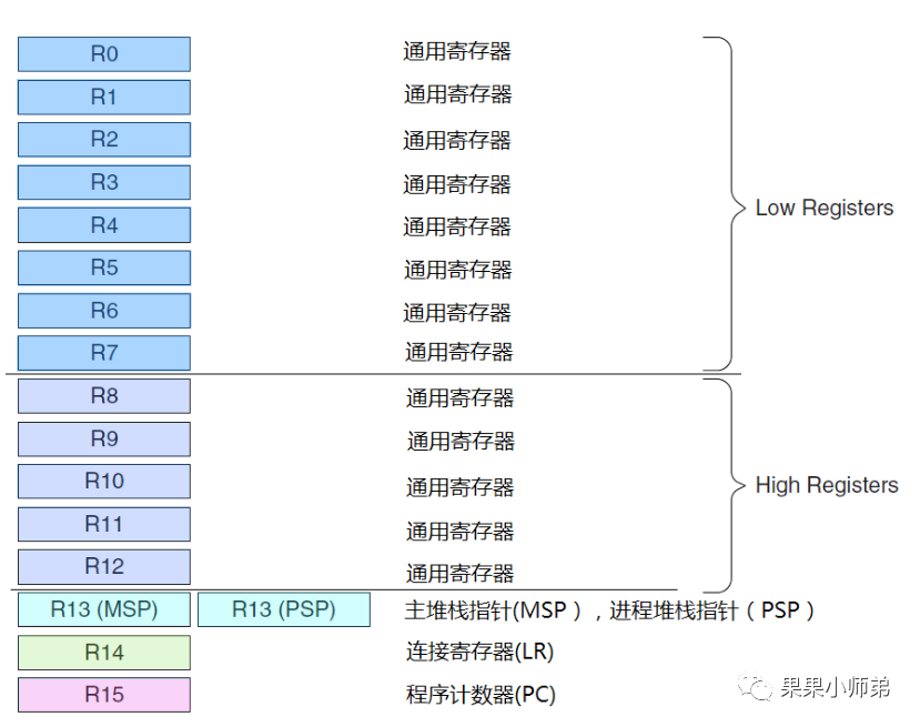
As we can see, the earlier registers are all general-purpose. They are divided into low registers (accessible by all instructions) and high registers (only accessible by a few 16-bit Thumb instructions). Why this division? In the early versions of the ARM core, the registers accessible by ARM and Thumb instructions were different, leading to this distinction. The later R13, R14, and R15 are the stack pointer, link register, and program counter register, respectively.
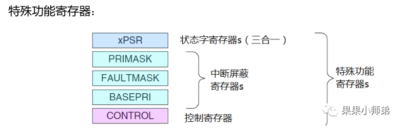
In addition, CM3 has some special registers.
Have you ever wondered how the CPU enters an interrupt? It essentially interrupts the previous task. After executing the interrupt, how does the CPU return to the original task without losing its state?
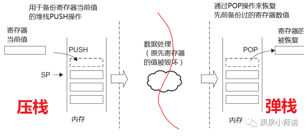
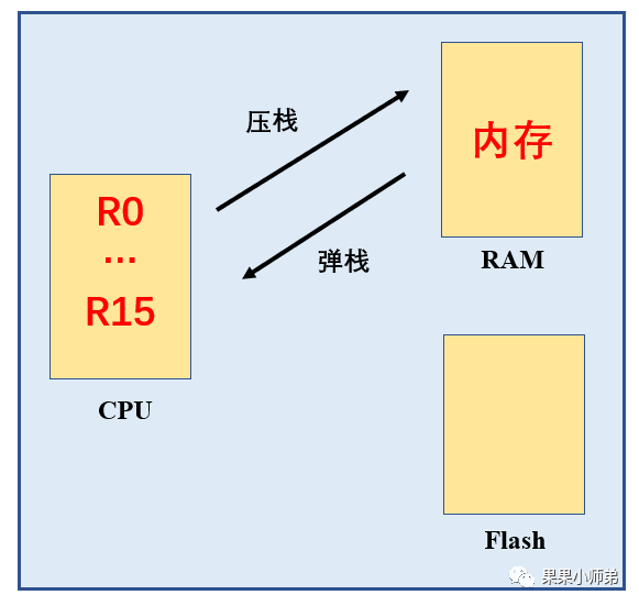
Before entering the interrupt, we first save the values of the CPU registers into memory, a process known as pushing to the stack. Then we run the interrupt service function, during which the CPU registers will be modified. However, this is not a problem because when the interrupt ends and we return to the original task, the previous CPU register values will be retrieved from memory, known as popping from the stack. This mechanism ensures that the original process’s data is not lost.
Now, let’s understand the stack-pushing order in CM3.

The above diagram shows the hardware stack-pushing order when Cortex-M3 enters an interrupt. This means that when it enters an interrupt, the hardware automatically pushes these registers onto the stack: PC pointer, xPSR special register, general-purpose registers R0 to R3, R12, and the LR link register (which saves the return address) will be pushed onto the stack in the order indicated in the third column.
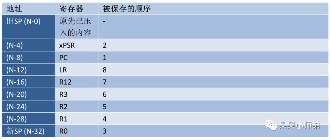
After successfully pushing onto the stack, when the interrupt completes and we return to the original process, the contents of the stack will be popped back into the CPU registers in the reverse order of how they were pushed. This means that LR is popped first, then the others in order, as the stack is last in, first out.
Earlier, we noted that the CPU has R0-R15 and several special registers. When the interrupt function arrives, the above registers are automatically pushed onto the stack by hardware, but there are also several that are pushed onto the stack by software. How do we understand this?
For instance:
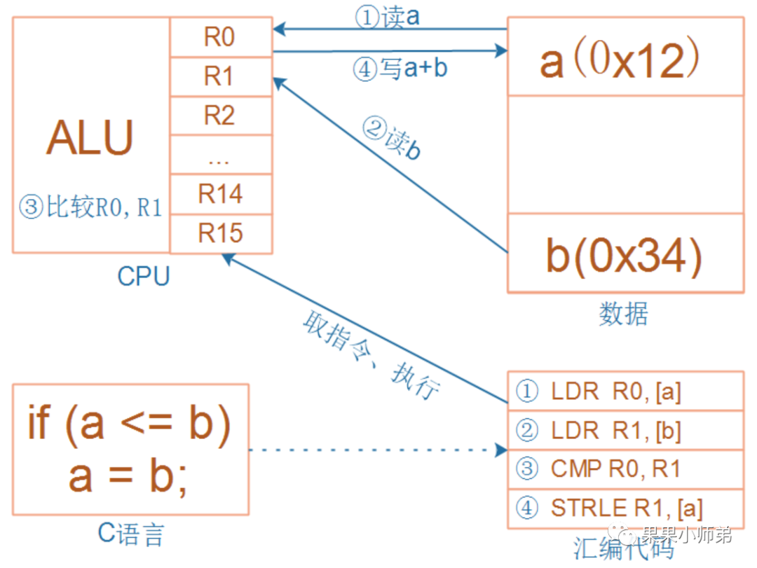
When the program executes
if(a<=b)
 a=b;
and suddenly an interrupt occurs. Every program ultimately converts to machine code, and the above C code can be converted to the assembly instructions on the right.
For these four instructions, they can be interrupted at any time. How do we ensure that the interrupted program can run correctly after the exception is handled?
These four instructions involve registers R0 and R1, and when the program is interrupted and resumes, R0 and R1 must remain unchanged. After executing the third instruction, the comparison result is stored in the Program Status Register (PSR), which must also remain unchanged during interruption and resumption. The memory for a and b must stay unchanged during the interruption and resumption. Maintaining the memory’s state is easy as long as the program does not go out of bounds. Therefore, the key is that R0, R1, and the Program Status Register must remain unchanged (and not just these registers):
-
Before handling the exception, save these registers onto the stack, known as saving the context, or pushing to the stack. -
After handling the exception, restore these registers from the stack, known as restoring the context, or popping from the stack.
Let’s provide another example:
void A()
{
    B();
}
For instance, if function A calls function B, function A should know that R0-R3 are used to pass parameters to function B; function B can modify R0-R3 freely; function A should not expect function B to save R0-R3; saving R0-R3 is function A’s responsibility. The same principle applies to LR and PSR; it is function A’s responsibility to save them, assisted by hardware.
For function B: if I use any of R4-R11, I will save them at the entrance of the function and restore them from memory before returning to ensure that R4-R11 remain unchanged for function A before and after the call.
Assuming function B is an exception/interrupt handler, if it can guarantee that R4-R11 remain unchanged, then during context saving, the hardware only needs to save R0-R3, R12, LR, PSR, and PC, which are the eight registers.
Next, let’s learn about the two special interrupt mechanisms in CM3. When CM3 begins to respond to an interrupt, three hidden currents surge within it:
-
Pushing to the stack: Push the values of eight registers onto the stack. -
Fetching the vector: Find the corresponding service program entry address from the vector table. -
Selecting the stack pointer MSP/PSP: Update the stack pointer SP, link register LR, and program counter PC.
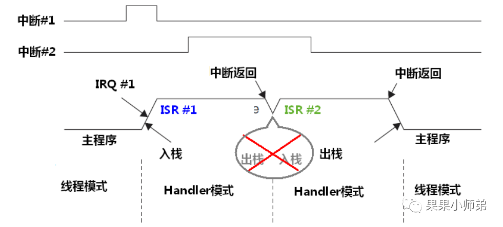
The first type is called tail-chaining interrupts
We know that entering an interrupt requires executing a push to the stack, and exiting an interrupt requires executing a pop from the stack. When two interrupts occur, after the first interrupt finishes, the second interrupt needs to execute. In the CM3 processor core, it will not execute the pop and push operations again. This saves the time for popping and pushing, essentially allowing the second interrupt to “bite off” the tail of the first interrupt. Hence, this is called a tail-chaining interrupt.
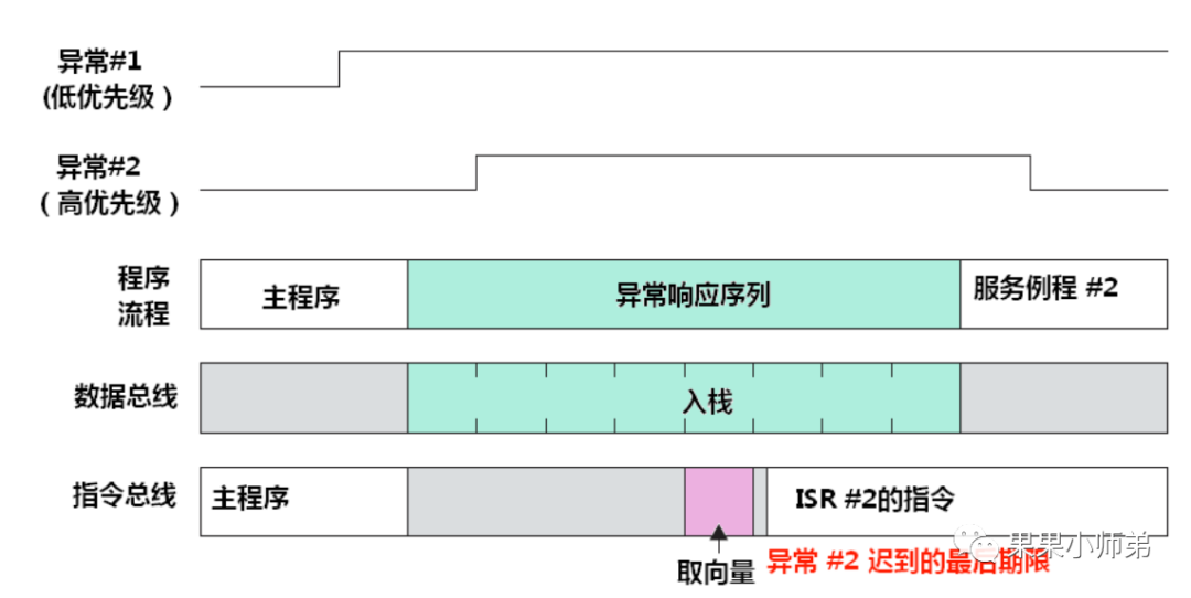
The second interrupt mechanism is called late arrival interrupts
Late arrival interrupts refer to when a high-priority task arrives while the previous low-priority task’s vector fetching has not yet completed (the previous low-priority task has not yet found the corresponding service program entry address from the vector table). In this case, the stack being pushed is for the high-priority task. Even if the high-priority interrupt arrives late, it can still use the stack pushed by the low-priority interrupt.
The interrupt table of the CM3 processor core
In real-time operating systems, the three interrupts frequently used are PendSV, Systick, and SVC.

In FreeRTOS, the Systick interrupt is used to provide the clock cycle for the real-time operating system. PendSV is a suspended interrupt used for task switching. SVC is only used once in FreeRTOS, specifically when starting the first process.
__asm void vPortSVCHandler( void )
{
/* *INDENT-OFF* */
    PRESERVE8

    ldr r3, = pxCurrentTCB   // Get the current task control block
    ldr r1, [ r3 ] // Use pxCurrentTCBConst to get the pxCurrentTCB address
    ldr r0, [ r1 ] // The first item in pxCurrentTCB is the stack top task
    ldmia r0 !, { r4 - r11 } // Manually push R4-R11, R14 registers onto the stack
    msr psp, r0    // Restore the task stack pointer
    isb
    mov r0, # 0
    msr basepri, r0 // Enable all interrupts
    orr r14, # 0xd
    bx r14
/* *INDENT-ON* */
}

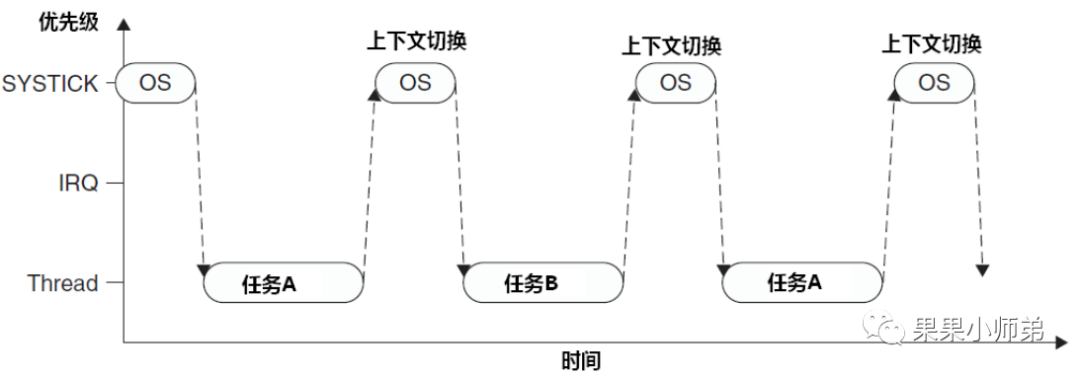
Some might wonder why we don’t switch tasks directly in the Systick interrupt but do so in PendSV. We can look at this:
If a Systick interrupt occurs while a previous interrupt is being executed (the IRQ is being executed), it will be interrupted, and then Systick will execute the context switch. At this point, it switches to task B, which has to wait until the next context switch to return to the original IRQ execution. This means the interrupt cannot be completed, resulting in significant delays. Therefore, this approach is not convenient and prone to errors.
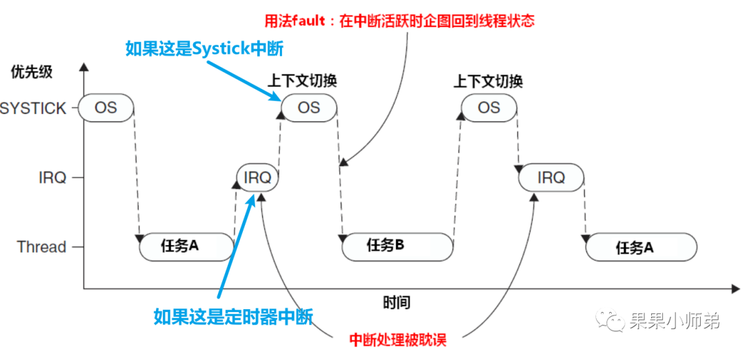
In this case, they devised a method where in the Systick interrupt, they check whether any interrupts are currently executing. If there are, they do not switch; if not, they proceed to switch. This can lead to another problem: if the interrupt time of this interrupt function is similar to that of Systick, for example, if this is a timer interrupt, both the Systick and this timer interrupt have a period of 1 millisecond, they may frequently face simultaneous arrivals. This could delay the process switching, causing delays, making this approach not ideal either.
Thus, the PendSV suspended interrupt was introduced
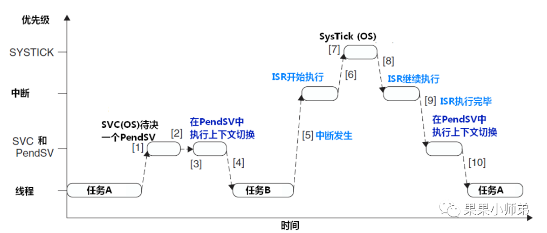
What are the benefits of this interrupt? We can see that in Systick, it only sets the PendSV interrupt bit, meaning it does not execute frequent switching operations. Instead, it waits until all interrupts have been executed before performing context switching in PendSV. This ensures timely task switching and timely interrupt execution. The PendSV exception automatically delays the context switch request until all other ISRs are completed. To implement this mechanism, PendSV must be programmed as the lowest priority exception. If the OS detects that an IRQ is active and is preempted by Systick, it will suspend a PendSV exception to delay the context switch.
So how is the process switch performed in PendSV? This is done using assembly language.
__asm void xPortPendSVHandler( void )
{
    extern uxCriticalNesting;
    extern pxCurrentTCB;
    extern vTaskSwitchContext;

    PRESERVE8

    mrs r0, psp// Save the current process stack pointer in R0
    isb

    ldr r3, =pxCurrentTCB // Get the current task control block
    ldr r2, [ r3 ] // Save the task control block address in R2

    stmdb r0 !, { r4 - r11 } // Manually push R4-R11, R14 registers onto the stack
    str r0, [ r2 ] // Write the current stack top address into the control block

    stmdb sp !, { r3, r14 }
    mov r0, #configMAX_SYSCALL_INTERRUPT_PRIORITY// Write the immediate value represented by this macro into R0, which is the highest priority interrupt the user wants to mask
    msr basepri, r0 // Write the value from R0 into the special register basepriority, which allows for detailed control of interrupts, masking interrupts below this priority while allowing higher priority interrupts
    dsb
    isb
    bl vTaskSwitchContext
    mov r0, #0
    msr basepri, r0 // Remove interrupt masking
    ldmia sp !, { r3, r14 } // Restore the current stack pointer from R3

    ldr r1, [ r3 ]
    ldr r0, [ r1 ] // Save the new task's stack top into R0
    ldmia r0 !, { r4 - r11 } // Manually pop R4-R11 and R14 registers from the stack
    msr psp, r0
    isb
    bx r14  // Return from the exception, hardware will automatically restore the remaining registers and use the process stack pointer.
    nop
/* *INDENT-ON* */
}
Now we have learned about the basic functionality of task switching in the FreeRTOS real-time operating system. However, to build a complete real-time operating system, many other features are needed, such as lists and list items, task notifications, low-power mode task control blocks, memory management, idle tasks, semaphore handling, software timers, event flag groups, and more.
References:
"Detailed Explanation of FreeRTOS Source Code and Application Development"
"Authoritative Guide to ARM Cortex-M3"
Let’s see how interrupts are specifically implemented in the program
The table below is from “Authoritative Guide to ARM Cortex-M3”
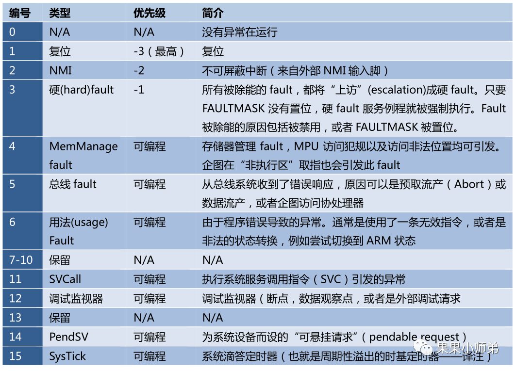
In Cortex-M3, there are 15 exception interrupts, corresponding to the STM32 as shown in the diagram below
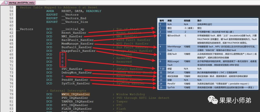
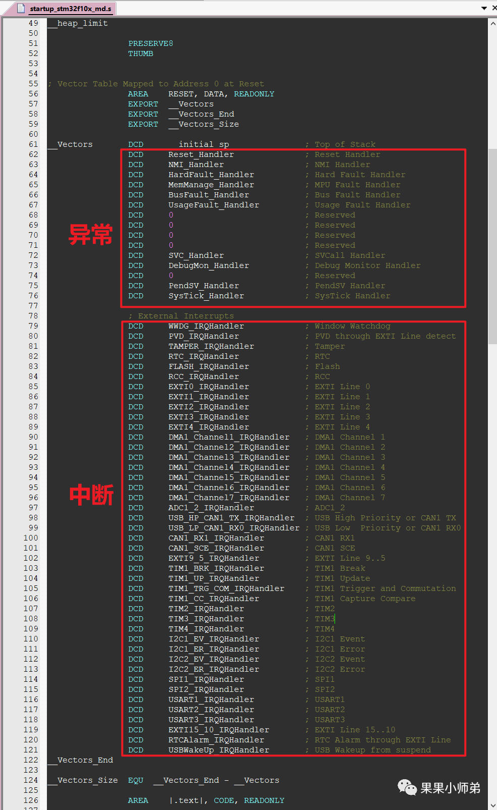
In the startup file, there are not only exceptions but also interrupts. In fact, interrupts are a type of exception. When we speak of interrupts, we often refer to signals sent by certain devices, such as the GPIO module: it sends a signal to the CPU, for example, after the I2C controller has sent data, or after the UART has received data, which will also generate an interrupt. Note that interrupts are a type of exception. Other exceptions generally include: Reset: also an exception, Various errors: also exceptions.
When our board resets, the CPU executes the Reset_Handler function in the interrupt vector table.
When the watchdog interrupt occurs, the CPU executes the WWDG_IRQHandler function in the interrupt vector table.
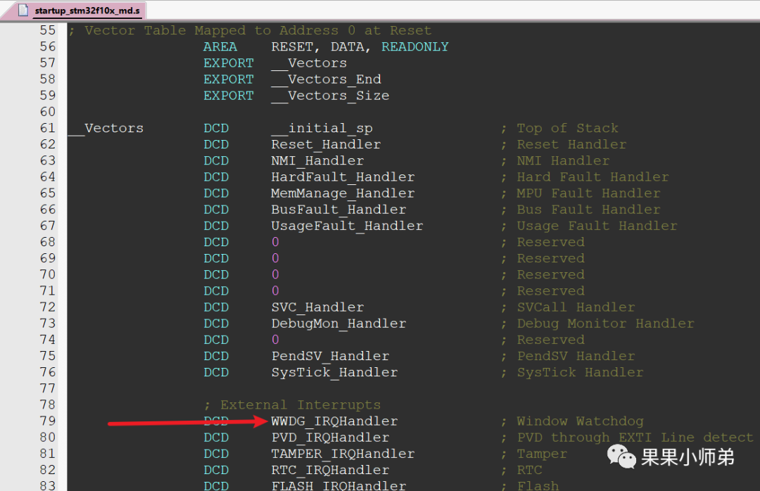
You may wonder how the CPU knows which function to jump to in the interrupt vector table?
This is determined by hardware because software has not yet started executing. The hardware identifies which exception or interrupt has occurred, and the software triggers the recovery process.
/**
  * @brief  This function handles NMI exception.
  * @param  None
  * @retval None
  */
void NMI_Handler(void)
{
}

/**
  * @brief  This function handles Hard Fault exception.
  * @param  None
  * @retval None
  */
void HardFault_Handler(void)
{
  /* Go to infinite loop when Hard Fault exception occurs */
  while (1)
  {
  }
}

/**
  * @brief  This function handles Memory Manage exception.
  * @param  None
  * @retval None
  */
void MemManage_Handler(void)
{
  /* Go to infinite loop when Memory Manage exception occurs */
  while (1)
  {
  }
}

/**
  * @brief  This function handles Bus Fault exception.
  * @param  None
  * @retval None
  */
void BusFault_Handler(void)
{
  /* Go to infinite loop when Bus Fault exception occurs */
  while (1)
  {
  }
}

/**
  * @brief  This function handles Usage Fault exception.
  * @param  None
  * @retval None
  */
void UsageFault_Handler(void)
{
  /* Go to infinite loop when Usage Fault exception occurs */
  while (1)
  {
  }
}

/**
  * @brief  This function handles SVCall exception.
  * @param  None
  * @retval None
  */
void SVC_Handler(void)
{
}

/**
  * @brief  This function handles Debug Monitor exception.
  * @param  None
  * @retval None
  */
void DebugMon_Handler(void)
{
}

/**
  * @brief  This function handles PendSVC exception.
  * @param  None
  * @retval None
  */
void PendSV_Handler(void)
{
}

/**
  * @brief  This function handles SysTick Handler.
  * @param  None
  * @retval None
  */
void SysTick_Handler(void)
{
}
Now you understand the interrupt flow of the MCU and the basic principles of RTOS, right?