STM32 has three different clock sources that can be used to drive the system clock (SYSCLK):
1: HSI oscillator clock (internal clock)
2: HSE oscillator clock (external clock, provided by the crystal)
3: PLL clock (Phase-Locked Loop clock)
These devices have the following two secondary clock sources:
(1) 40kHz low-speed internal RC, which can be used to drive the independent watchdog and drive the RTC through program selection. The RTC is used to automatically wake the system from sleep/standby mode.
(2) 32.768kHz low-speed external crystal can also be used to drive the RTC (RTCCLK) through program selection.
When not in use, any clock source can be independently turned on or off, thereby optimizing system power.
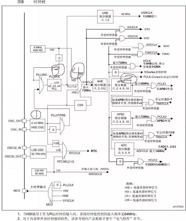
Below is an example with an external crystal of 8M and a system clock of 72M.
The STM32 system clock initialization process is as follows:
1. Reset and configure the vector table;
2. Enable external high-speed interrupt HSEON and wait for it to be ready;
3. RCC->CFGR=0X00000400; set APB1, as it is too late to set APB1 after the previous settings, so it must be divided first, because APB1 must not exceed 36MHz, with a maximum of 72MHz before, hence the division;
4. RCC->CFGR|=PLL<<18; set the PLL multiplication factor, which is the PLLMUL of the clock tree;
5. RCC->CFGR|=1<<16; select HSE as the PLL input;
6. FLASH->ACR|=0x32; FLASH 2 wait states
7. RCC->CR|=0x01000000; enable PLL and wait for it to be ready;
8. RCC->CFGR|=0x00000002; set PLL as the system clock and wait for it to be ready.
The clock tree is as follows: the general process is as labeled in the clock tree.
The STM32 system clock initialization code is as follows:
void Stm32_Clock_Init(u8 PLL)
{
unsigned char temp=0;
MYRCC_DeInit(); // Reset and configure the vector table
RCC->CR|=0x00010000; // Enable external high-speed clock
while(!(RCC->CR>>17));// Wait for external clock to be ready
RCC->CFGR=0X00000400; // APB1=DIV2;APB2=DIV1;AHB=DIV1; // Divide by 2
PLL-=2;// Offset by two units, refer to the STM32 reference manual
RCC->CFGR|=PLL<<18; // Set the PLL value, 2~16
RCC->CFGR|=1<<16; // PLLSRC ON
FLASH->ACR|=0x32; // FLASH 2 wait states
RCC->CR|=0x01000000; // PLLON
while(!(RCC->CR>>25));// Wait for PLL to lock
RCC->CFGR|=0x00000002;// PLL as system clock
while(temp!=0x02) // Wait for PLL to be set as system clock successfully
{
temp=RCC->CFGR>>2; // Continuously query the register to see if the system clock is set successfully
temp&=0x03;
}
}
When running bare metal programs, using the chip’s built-in SysTick timer for delays is a relatively accurate delay method.
SysTick: system heartbeat timer, provides system beats, can be used as an independent delay timer in bare metal programs.
It has four registers:
STK_CSR, 0xE000E010 — Control register
STK_LOAD, 0xE000E014 — Reload register
STK_VAL, 0xE000E018 — Current value register
STK_CALRB, 0xE000E01C — Calibration value register
Delay programming principles:
The SysTick timer is a 24-bit decrementing counter. After setting the initial value and enabling it, it will decrement by 1 every system clock cycle.
When it counts down to 0, it will automatically reload the initial timing value from the RELOAD register. As long as the enable bit in the SysTick control and status register is not cleared, it will run indefinitely.
Delay programming steps:
1. Calculate how many clock cycles are needed to generate 1us fac_us;
2. Calculate the value of the RELOAD register, which is the number of clock cycles needed to produce the corresponding delay:
RELOAD=fac_us * nus
3. Start counting;
4. Loop to check the flag bit indicating counting down to 0;
5. Clear the counter and turn off the timer.
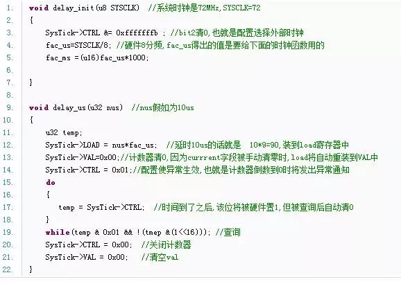
Register version code annotation (can also be seen from the clock tree above):
Using an external 8M clock, the frequency coming out of the PLL is 72M, after AHB prescaling it is 72M,
the SysTick is fixed at HCLK clock of 1/8, which is 9M, so a delay of 1us is 9 clock cycles.
The code is as follows:
Another point to note:
The LOAD register is 24 bits, with a maximum value of 0xffffff.
Then the maximum delay calculation formula is:
nms<=0xffffff*8*1000/SYSCLK (SYSCLK in Hz)
Thus, the maximum value of nms is 1864.135ms, that is, 1864 milliseconds.
Source: http://blog.chinaunix.net/uid-29270628-id-4419871.html