STM32 Beginner Tutorial: Light Up Your First LED with CubeIDE
In the journey of learning microcontrollers, the classic “Hello World” is not about printing text on a screen, but rather lighting up an LED. This may seem simple, but it is an important step into the embedded world. In this tutorial, we will use the STM32 microcontroller and the CubeIDE development environment to guide you from zero to achieving this small goal.
What is STM32? Why Use It?
STM32 is a series of microcontrollers based on the ARM Cortex-M architecture launched by STMicroelectronics. They are not only powerful and feature-rich but also have a good development ecosystem. CubeIDE is a one-stop development tool provided by ST, integrating code editing, compilation, debugging, etc., which is very friendly for beginners.
Lighting up an LED is the first project for getting started with STM32, and the core of it is mastering how to operate GPIO (General Purpose Input/Output). GPIO is like the “hands and feet” of the microcontroller, allowing interaction with the outside world, such as lighting up an LED or reading the state of a button.
1. Preparation Work
Before starting, you need to prepare the following hardware and software:
Hardware
-
STM32 Development Board (recommended STM32F103C8T6 or STM32F401 series)
-
USB Data Cable (for connecting the development board to the computer)
-
LED and Current Limiting Resistor (usually around 220Ω)
-
Breadboard and Dupont Wires (for easy circuit assembly)
Software
-
STM32CubeIDE (download from: STMicroelectronics official website)
-
ST-Link Driver (some development boards require separate installation)
2. Basic Concept Explanation: The Relationship Between GPIO and LED
What is GPIO?
GPIO (General Purpose Input/Output) are the general input and output pins of a microcontroller. They can be understood as the “interface” for communication between the microcontroller and external devices. GPIO has two states:
-
Output Mode: Used to control external devices, such as lighting up an LED.
-
Input Mode: Used to read the state of external devices, such as detecting if a button is pressed.
The Relationship Between LED and GPIO
An LED is essentially a component that requires current to emit light. When GPIO outputs a high level (for example, 3.3V), current flows through the LED, and it will light up. To prevent excessive current from burning out the LED or GPIO, we need to connect a current-limiting resistor in series in the circuit.
In simple terms, the core operation of lighting up an LED is controlling the GPIO’s level output.
3. Circuit Connection
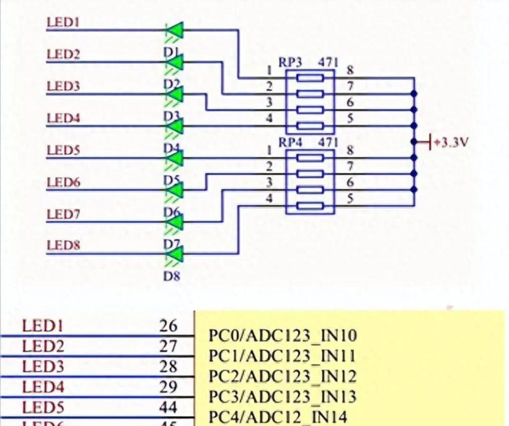
Circuit Schematic
STM32 GPIO -----> Current Limiting Resistor -----> LED -----> GND
-
GPIO Pin: Choose any GPIO pin on the development board (for example, PA5).
-
Current Limiting Resistor: Recommended value is 220Ω.
-
LED Polarity: The longer leg connects to the current limiting resistor, and the shorter leg connects to GND.
Actual Wiring Diagram
-
Connect the longer leg of the LED through a 220Ω resistor to the PA5 pin on the development board.
-
Connect the shorter leg of the LED directly to the GND pin.
Notes:
-
Ensure the LED polarity is correct; otherwise, the LED will not light up.
-
Before wiring, the development board should be powered off to avoid short circuits.
4. Configure GPIO Using CubeIDE
Create a New Project
-
Open STM32CubeIDE, click File -> New -> STM32 Project.
-
In the pop-up window, select your development board model (e.g., STM32F103C8T6), then click Next.
-
Enter the project name (e.g.,
LED_Blink), and click Finish.
Configure GPIO as Output Mode
-
After the project is created, the CubeMX interface will open automatically.
-
In the Pinout & Configuration tab, find the PA5 pin and set it to GPIO_Output.
-
Switch to the Configuration tab to check the default state of GPIO (it is recommended to set it to Push-Pull mode, low-speed output).
-
Click Project -> Generate Code to generate the initialization code.
Notes:
-
The default state of GPIO is input mode; if it is not configured correctly as output, the LED will not light up.
-
If you are unsure which pin to use, refer to the schematic of the development board.
5. Write Code to Light Up the LED
Main Program Code
In the generated project, open the Src/main.c file and find the following code segment:
1/* USER CODE BEGIN 2 */
2// After initialization, we can write our own code here
3HAL_GPIO_WritePin(GPIOA, GPIO_PIN_5, GPIO_PIN_SET); // Set PA5 to high level, light up LED
4/* USER CODE END 2 */
The complete code is as follows:
 1#include "main.h"
 2
 3int main(void)
 4{
 5  HAL_Init(); // Initialize HAL library
 6  SystemClock_Config(); // Configure system clock
 7  MX_GPIO_Init(); // Initialize GPIO
 8
 9  while (1)
10  {
11    // Light up LED
12    HAL_GPIO_WritePin(GPIOA, GPIO_PIN_5, GPIO_PIN_SET);
13    HAL_Delay(500); // Delay 500ms
14
15    // Turn off LED
16    HAL_GPIO_WritePin(GPIOA, GPIO_PIN_5, GPIO_PIN_RESET);
17    HAL_Delay(500); // Delay 500ms
18  }
19}
Code Explanation
-
HAL_GPIO_WritePin(GPIOx, GPIO_PIN_y, GPIO_PIN_SET): Control the specified GPIO pin to output high level. -
HAL_GPIO_WritePin(GPIOx, GPIO_PIN_y, GPIO_PIN_RESET): Control the specified GPIO pin to output low level. -
HAL_Delay(ms): Delay function, unit in milliseconds.
Through this code, we achieve the blinking effect of the LED.
6. Download Code to the Development Board to Run
-
Connect the development board to the computer using the USB data cable.
-
In CubeIDE, click Project -> Build Project to compile the code.
-
Click Run -> Debug to flash the program to the development board.
-
If everything is normal, the LED will start blinking according to the logic of the code.
Notes:
-
If you cannot connect to the development board, check if the correct ST-Link driver is installed.
-
Ensure that the GPIO pin in the code matches the actual wiring.
7. Common Problems and Solutions
LED Not Lighting Up
-
Check Wiring: Ensure the LED polarity is connected correctly.
-
Check GPIO Configuration: Confirm the pin mode is set to output.
-
Check Code: Ensure the operated pin matches the actual wiring.
STM32CubeIDE Cannot Detect Development Board
-
Driver Issue: Reinstall the ST-Link driver.
-
Cable Issue: Try replacing the data cable.
LED Brightness Too Low or Burned Out
-
Current Limiting Resistor Too Small or Not Connected: Replace with a 220Ω or larger resistor.
8. Practical Suggestions
-
Try changing the delay time in the code to observe the change in LED blinking speed.
-
Use other GPIO pins to modify the code to light up multiple LEDs.
-
Further learn how to control the LED state through buttons to achieve simple interaction.
Lighting up an LED is just the first step in learning STM32. Next, you can explore button inputs, interrupts, PWM, and other functions, gradually mastering the core skills of microcontroller development. Remember: every small project is a step towards progress; steady and steady wins the race!