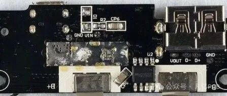
When disassembling power boards or designing power-related PCBs, we often encounter structures like this:
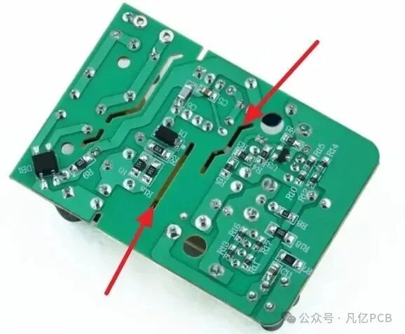
Figure 1: Common slot hole structure on power PCBs
Many people think these slot holes are just for aesthetics or mechanical structure needs. In fact, their true function is closely related to electrical safety, and the key lies in one concept—creepage distance.
What is “creepage distance”?
Creepage distance refers to:
The shortest “leakage path” distance between two conductive bodies along the insulating surface.
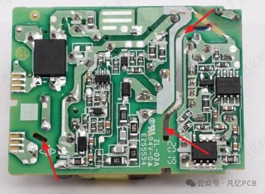
Figure 2: Schematic diagram of creepage path and insulation
For a vivid example: it’s like an ant, crawling from one charged conductor to another, only able to walk along the insulating surface, and the shortest path it takes is the “creepage distance”.
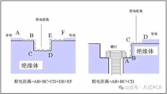
Figure 3: Difference between creepage distance and air gap
🚫 Key distinctions:
-
Creepage distance: travels along the insulating surface (affected by dust/pollution)
-
Air gap: the shortest straight-line distance in air (not touching the surface)
Why can slotting increase creepage distance?
In power boards, high-voltage components must be isolated from low-voltage components. However, sometimes, due to space constraints, the distance between these components may not meet the required creepage distance.
What to do in this case? The solution is: to create slots!
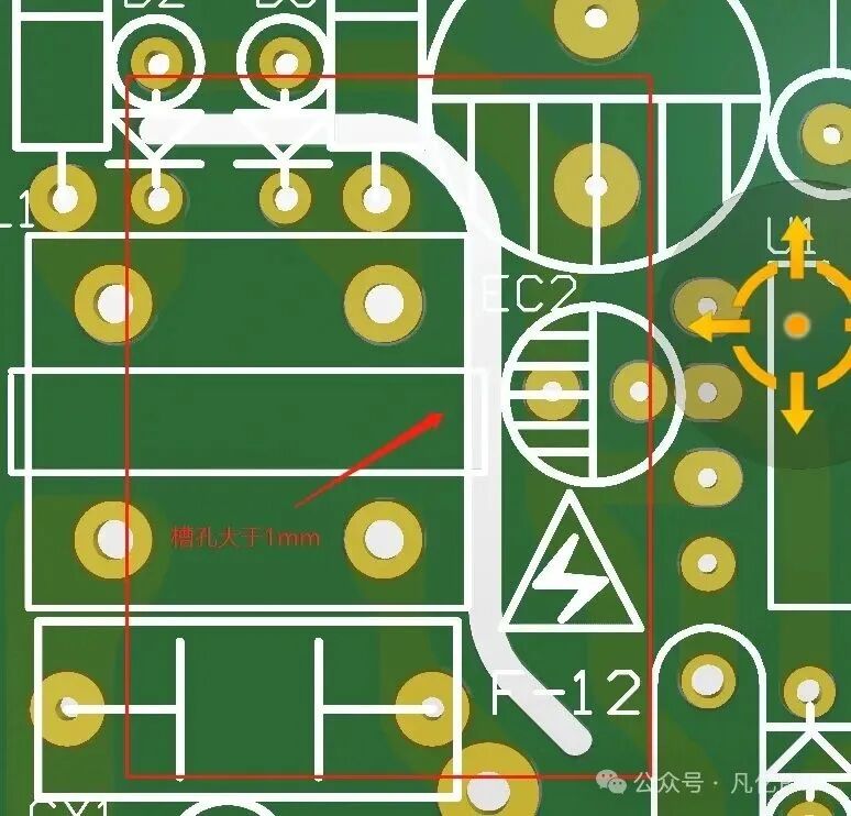
Figure 4: Schematic diagram of increasing creepage distance by slotting on PCB
By removing the substrate in the middle, it is equivalent to “the ant cannot pass through,” which effectively artificially extends the surface creepage distance and also effectively cuts off the discharge path on the insulating surface, thereby enhancing insulation.
Considerations for slot design:
-
Slot width should be >1mm
-
High-voltage areas should avoid copper pouring
-
Slot positions should avoid signal paths or critical routing areas
-
Slot edges should be smooth to prevent sharp corners from causing discharge
Examples of application scenarios:
-
AC-DC switching power supply modules
-
High-voltage drive circuits in industrial controllers
-
Mixed voltage systems (e.g., 220V and 5V on the same board)
Whether to meet safety standards or to address pollution levels and insulation grades, designing slot structures reasonably is an indispensable step in power PCB design.
Conclusion:
Do not overlook the “slot holes” on power boards; they are not unnecessary decorations, but an important part of ensuring your product passes safety tests!
Remember this phrase:
A good design is not only functional but also safe and reliable!

Note:This article is an original piece by Fanyi Education, please indicate the source when reprinting!For submissions/recruitment/advertising/course cooperation/resource exchange, please add WeChat: 13237418207
Can vias be placed on pads? A detail that PCB designers must pay attention to!
2025-07-01
Too many people get it wrong! Design stamp holes like this to avoid issues during board cutting (full illustration)
2025-06-09
“5G Mobile Phone Mainboard PCB 16-Layer Advanced Design 1-on-1 Practical Training”
2025-06-06

A few images to help you easily understand how to use PCB design to improve heat dissipation issues!
2025-06-16