A programmable logic control relay is a “programmable”, “general-purpose”, and “intelligent” control relay. Different manufacturers have different product names, such as the electronic control relay “easy” from Germany’s Weidmüller; the intelligent control relay “BoxX” from Turck; the general logic module “LOGO!” from Siemens; Schneider Electric’s “Zelio Logic” logic controller; the FL1D type intelligent application controller from Japan’s Izumi Electric; the programmable relay “ZEN” from OMRON; and the programmable controller “ALPHA” from Mitsubishi.
Structure and Principle of Programmable Logic Control Relay
The programmable logic control relay stores some typical relay logic control programs in its internal memory in advance. Through user program combinations and calls, it can achieve some simpler logic control and sequential control functions. The user program can be programmed using ladder diagram or function block language via the panel, which is intuitive and easy to understand. It uses buttons, switches, and other input signals to execute programs sequentially, performing arithmetic operations, logic operations, analog operations, timing, counting, frequency measurement, etc. Additionally, it has functions such as parameter display, communication, and simulation operation. Its integrated internal software functions and programming software can replace traditional relay logic circuits composed of relays, contactors, and timers, and it has strong anti-interference suppression capabilities. Moreover, its hardware is standardized, and changing the control function only requires changing the program. Therefore, in relay logic control systems, it can “replace hardware with software” to substitute for timing relays, intermediate relays, counters, contactors, and timers, simplifying circuit design and achieving more complex logic control, even functions that traditional relay logic control methods cannot accomplish. Thus, it is widely used in industrial automation control systems, small machinery and equipment, building electrical systems, etc. In intelligent buildings, it is suitable for controlling smart home systems, lighting systems, heating and ventilation systems, doors, windows, fences, and moving doors. The new products also feature an LCD display human-machine interface that can display up to 32 segments of text, with each text containing a maximum of 64 characters. Input/output points can be expanded locally and remotely, and can also be integrated into higher-level automation systems through AS-i, PROFIBUS, CANopen, or DeviceNet network modules.
The basic model of the programmable logic control relay has a width of 72mm, equivalent to the size of 8 modules. The extended and bus versions have a width equivalent to 14 modules and can be mounted on a 35mm DIN rail. The basic model products from different brands are generally similar in appearance. Taking the “easy” from Weidmüller as an example, the appearance and panel function layout of the basic model are shown in the figure below.
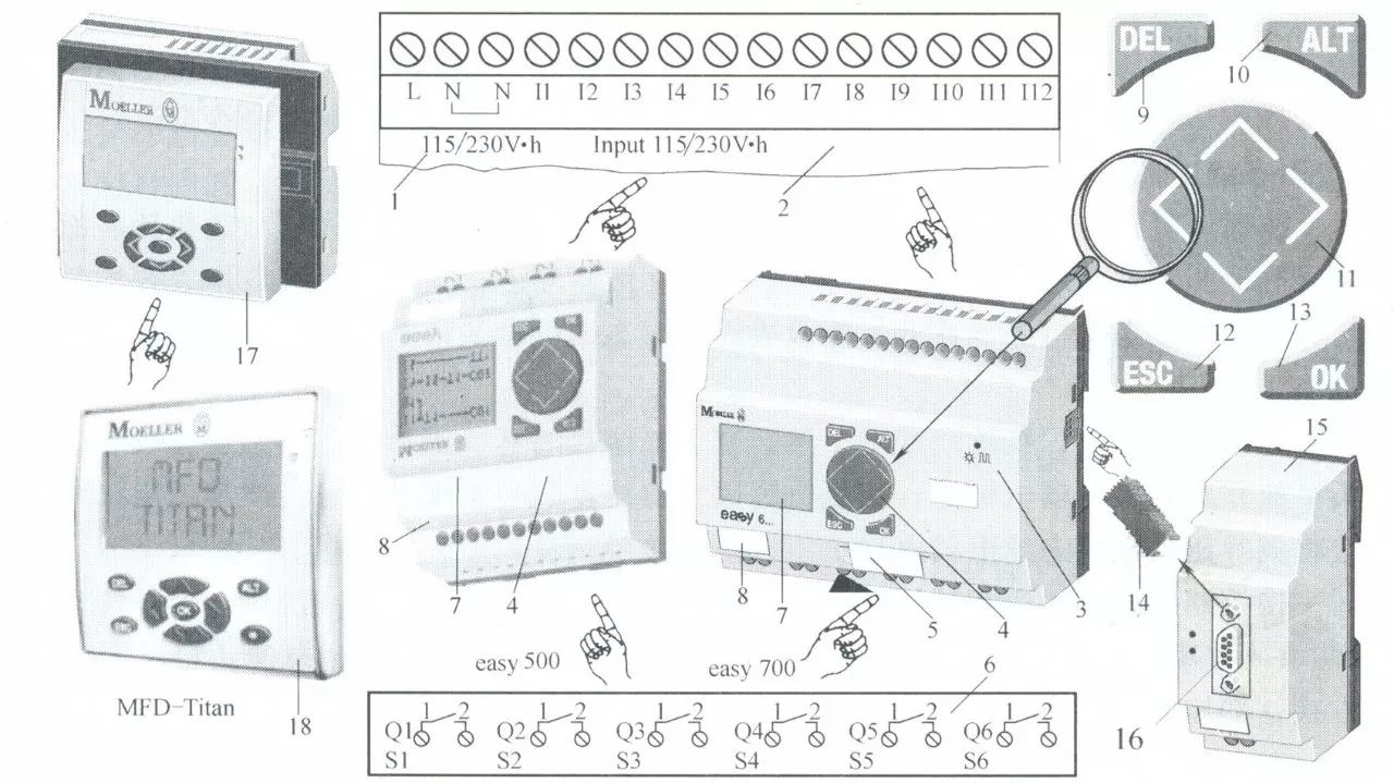
The easy500/700/800 series and MFD-Titan multifunction display have functions such as mathematical operations, logic control, timing and counting, timed switches, PID control, operator and display, high-speed counting, frequency measurement, and high-speed incremental encoder processing, data storage, and communication networking.
The easy500 control relay has 8 digital input terminals, 4 relay output terminals, or can choose 4 transistor output terminals. It can program up to 128 lines of programs, with a maximum of 3 contacts and 1 coil per line, and has 16 operational and informational texts. It can optionally have 2 analog input terminals (10-bit), 2 high-speed input terminals at 1kHz, and can handle up to 12 I/O signals.
The easy700 control relay has 12 digital input terminals, 6 relay output terminals, or can choose 8 transistor output terminals. It can program up to 128 lines of programs, with a maximum of 3 contacts and 1 coil per line, and has 16 operational and informational texts. It can optionally have 4 analog input terminals (10-bit), 2 high-speed input terminals at 1kHz, 1 I/O expansion module or bus module, and can handle up to 40 I/O signals.
The easy800 control relay has 12 digital input terminals, 6 relay output terminals, or can choose 8 transistor output terminals and 1 analog output terminal. It can program up to 256 lines of programs, with a maximum of 4 contacts and 1 coil per line, and has 32 operational and informational texts. It can optionally have 4 analog input terminals (10-bit), 4 high-speed input terminals at 3/5kHz, 1 I/O expansion module or bus module. With the built-in network interface easy-Net, it can network between devices, with a maximum of 8 stations and a maximum communication distance of 1000m. All stations can be locally expanded via the easy-Link connector, allowing the easy800 control relay to handle up to 320 I/O signals.
The MFD (Multi-Function Display) combines HMI and easy control relays, consisting of a display/operator module, power/CPU module, and optional I/O modules. In addition to having the same functions as the easy800 control relay, it mainly features full graphics and backlit display capabilities, and can be used as a compact HMI control device for display, operation, programming, and parameter setting. Furthermore, the MFD-Titan can communicate point-to-point with an easy800 or another MFD-Titan via a serial communication interface. The MFD-Titan multifunction display has 12 digital input terminals, 4 relay output terminals, or can choose 4 transistor output terminals, 1 analog output terminal, and can program up to 256 lines of programs, with a maximum of 4 contacts and 1 coil per line, featuring a 64×132 pixel full graphic, backlit display, requiring 24KB memory per frame. It can optionally have 4 analog input terminals (10-bit), 4 high-speed input terminals at 3/5kHz, 1 I/O expansion module or bus module, and can network between devices, with a maximum of 8 stations and a maximum communication distance of 1000m. The MFD-Titan multifunction display is suitable for large control projects.
The power supply for the easy500/700/800 series and MFD-Titan multifunction display is AC115/240V or DC12/24V. The basic model of easy typically has a DC12/24V, AC115/240V input for DI, while DO typically has a DC12/24V, AC115/240V transistor or relay output, with a maximum relay output current of 10A. The analog input/output type is 0-10V. High-speed input terminals and optional analog input terminals are only suitable for DC power supply types; the AC type does not have them.
The easy800 control relay and MFD-Titan multifunction display have all the performance characteristics of PLCs. Using the built-in network interface easy-Net, it can connect up to 8 devices, and all stations can be locally expanded via the easy-Link connector, allowing for a maximum of 320 I/O points. The control system can consist of a single device or multiple distributed devices. The maximum network coverage distance is 1000m. Additionally, through bus connection modules, devices can be integrated into higher-level automation systems, and the connectable bus systems include PROFIBUS-DP, CANopen, DeviceNet, and AS-i. The MFD-Titan supports all functions of easy800 and features a full graphic display that can show fault information and operational processes in graphical or textual form. The function keys on the MFD-Titan allow for online display and modification of set values. Like the easy800, the MFD-Titan also has functions for mathematical operations, high-speed counting, frequency measurement, high-speed incremental encoder processing, data storage, or network communication.
The user program for the easy control relay uses ladder diagram language, which can be entered using just four programming keys, as shown in the figure above, and the input status can be observed via the display. The user program for Schneider Electric’s “Zelio Logic” logic controller uses a ladder diagram language similar to that of the easy control relay, while Siemens’ “LOGO!” uses function block language for program input.
Overview of Functions and Applications of Programmable Logic Control Relay
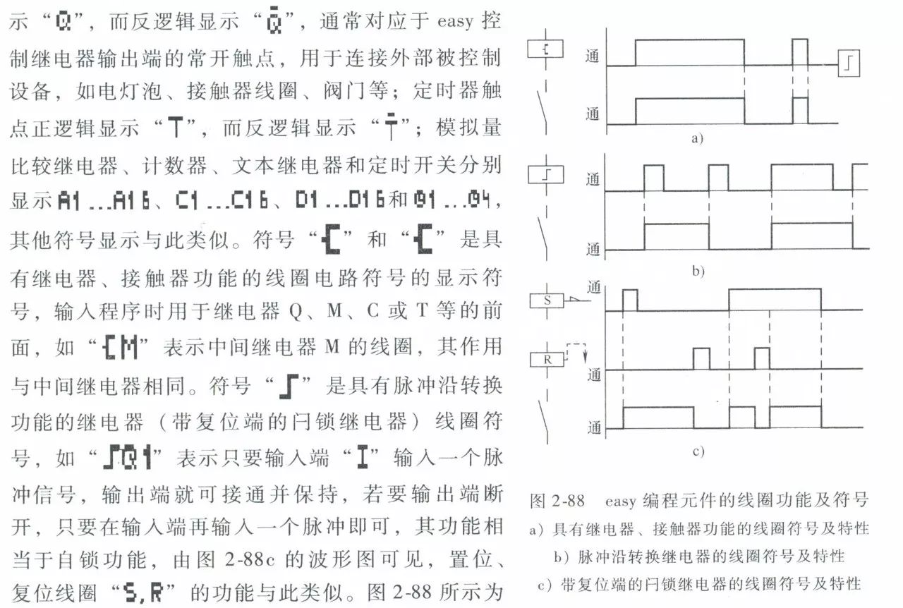
Coil circuit symbols and display symbols and characteristics.
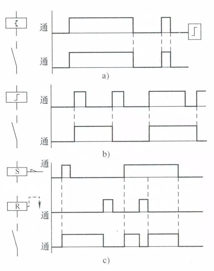
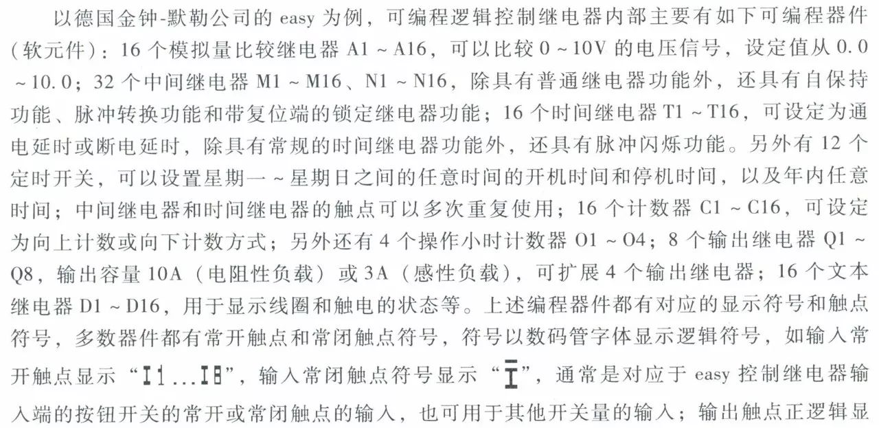
Supplementary Image: Due to difficult symbols in the previous text, the editor has uploaded the book content in image form. We hope everyone understands.
When using the easy control relay, simply convert the designed relay logic control diagram into the corresponding ladder diagram using the appropriate symbols specified in the easy control relay user manual. Input it into the easy via the programming keys on the panel. Once input is complete, offline simulation operation can be performed, and the display can show the flow and working status of the current. The following figure is an example of a simple motor control circuit, illustrating only a part of it for clarity.
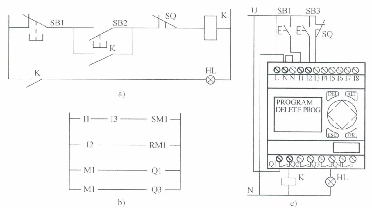
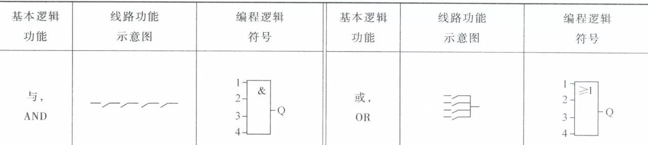
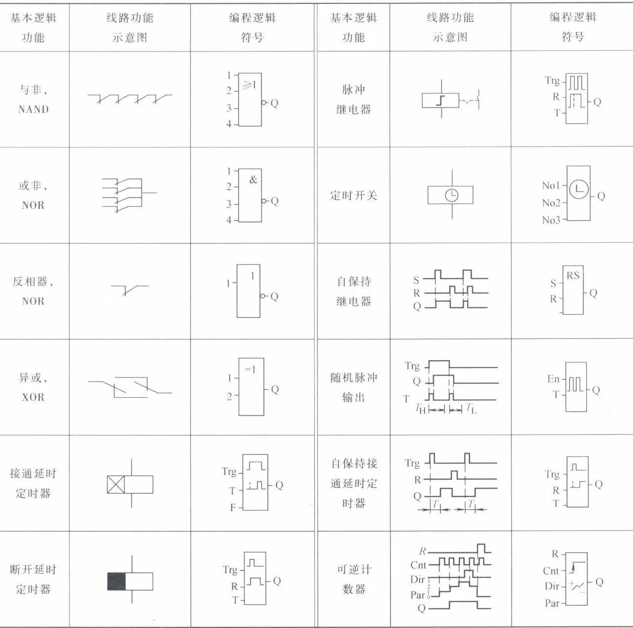
Figure a shows the relay logic control circuit, figure b shows the ladder diagram input into easy, and figure c shows the wiring schematic. The ladder diagram uses the latch relay function with a reset terminal to achieve this, where SM1 is the self-locking coil of the intermediate relay M1, and RM1 is its reset coil; I1 and I2 are the input signals from the buttons, and I3 is the limit switch. The buttons and limit switch are connected to the input control terminals of the easy; the contactor and indicator light are connected to the output terminals of the easy. When button SB1 (I1) is pressed, SM1 self-locks. If the limit switch (I3) is closed at this time, the output contact Q1 is energized, turning on the contactor’s coil power, and the motor runs; output contact Q2 is also energized, lighting the indicator. To stop, button SB2 (I2) is pressed, resetting M1 and stopping the motor. As shown in the figure, its logical relationship is very clear and easy to understand. It is important to note that the ladder diagram compiled in the figure is not unique; other programming elements can also be used to create a ladder diagram with the same function. Due to space limitations, no further elaboration will be made; please refer to the product user manual if needed. The table below lists some commonly used logic function blocks for programmable logic control relays for reference, and the symbols for logic function blocks of various brands are generally similar, with slight differences.
END
Source: “Principles and Control Technology of Common Low Voltage Electrical Appliances”
Click the image to quickly purchase the book
If you think it’s good, please share and like!

↓
Welcome to leave comments or feedback
Click “Read Original” at the end of the article to purchase the book

Long press the QR code to follow us