Display Interfaces: DBI/DPI/DSISTM32 models are numerous, covering display driving capabilities from low to high. See the image: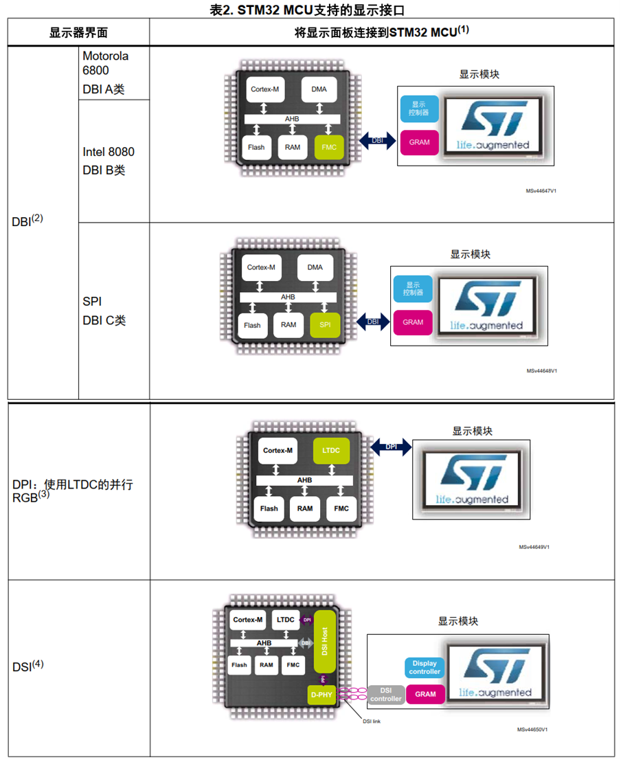 It can be seen that MIPI DBI/DPI/DSI are all included, so why are there these situations? The table below explains the reasons:
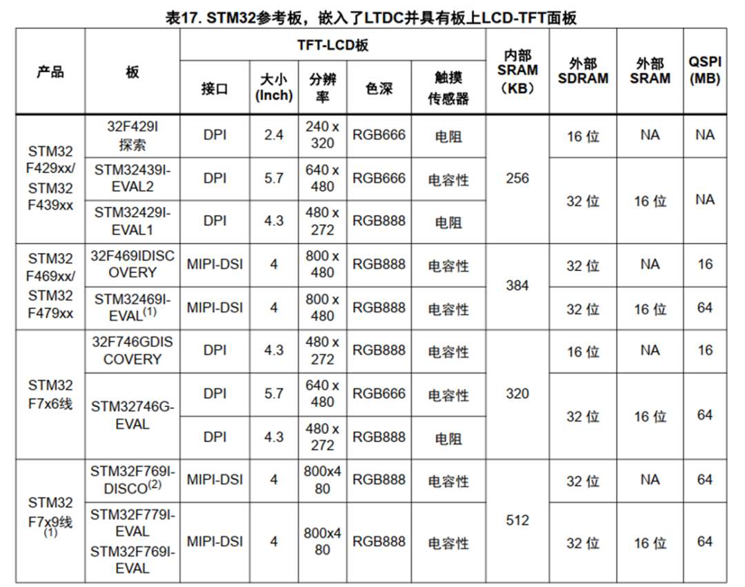 It can be seen that the driving capability of DPI is weaker than that of DSI. The above table does not include DBI, but from the first image, we know that DBI is based on a low-speed interface, and its driving capability is even weaker.MIPI-DBI (Display Bus Interface) is the first display standard released by the MIPI Alliance, divided into three types as shown in the first image. MIPI-DBI is used to connect to displays with integrated Graphics RAM (GRAM). Pixel data is updated in the display’s local GRAM.
MIPI-DPI (Display Parallel Interface) standardizes the interface through the LTDC controller. Its RGB signals are used in conjunction with synchronization signals (HSYNC, VSYNC, EN, and LCD_CLK). DPI is used to connect to displays without a frame buffer. Pixel data must be streamed to the display in real-time. Its real-time performance is very good, but it requires the MCU to have a large bandwidth to support the display.
MIPI-DSI (Display Serial Interface) uses multi-channel differential links; it uses the standard MIPI D-PHY as the physical link. DSI encapsulates DBI or DPI signals and sends them to D-PHY via the PPI protocol.Integrating the MIPI-DSI controller simplifies PCB design, reduces pin count, lowers EMI (electromagnetic interference), and decreases power consumption.LTDC’s DPI Interface and ConfigurationThe DPI-based interface is driven upstream by hardware LTDC, interfacing with the DPI interface and downstream (screen) or DSI HC (Host Controller). A basic wiring for DPI is as follows: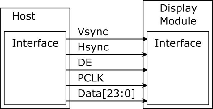 The LTDC block diagram is as follows:
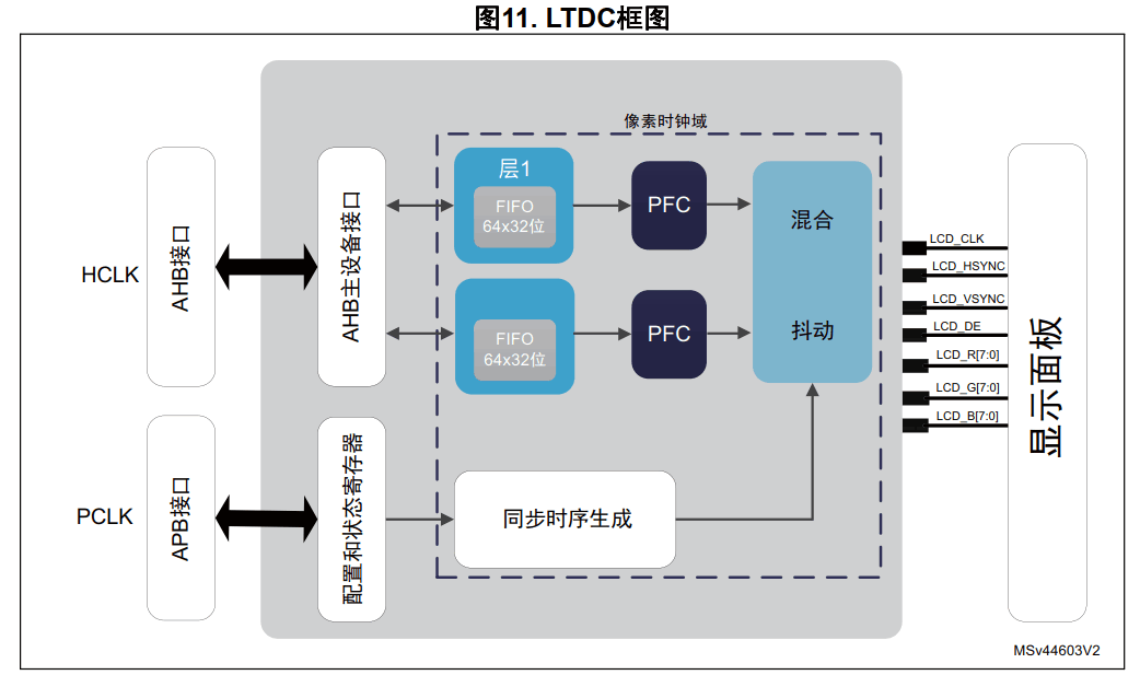 LTDC is a master device on the AHB architecture, capable of reading from internal and external memory. LTDC has two independent layers, each with its own FIFO, making display more flexible.
The LTDC controller automatically extracts graphic data from the frame buffer at AHB bus speed. It then stores the graphic data in one of the internal layer FIFOs, subsequently driving it to the display.
This system architecture allows graphics to be built and drawn to the screen without any CPU intervention, while the Chrom-Art Accelerator® (DMA2D) prepares the next image.
The LTDC interface is integrated into the smart architecture, allowing:
-
LTDC automatically reads graphic data from the frame buffer (which can be internal memory, such as internal flash, internal SRAM, FMC_SDRAM, or Quad-SPI) and drives it to the display.
-
As an AHB master device, DMA2D can offload CPU from graphics-intensive tasks.
-
Even in sleep mode when the CPU is not running, LTDC can continue to display graphics.
-
The multi-layer AHB bus architecture improves memory throughput and performance.
Programming LTDC mainly involves setting DPI timing, and the following is a typical DPI timing diagram:
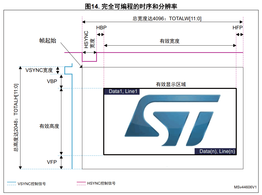
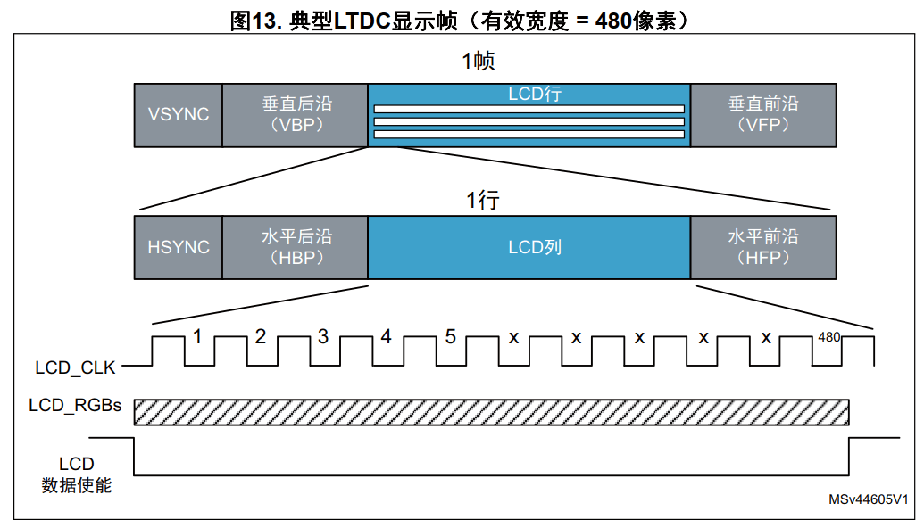
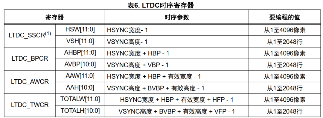
The corresponding timing registers for LTDC are as follows:
Chrom-Art Accelerator® (DMA2D)
LTDC is responsible for driving the display image to the screen, while DMA2D is used to accelerate the generation of display images. DMA2D is a 2D image processing accelerator on STM32. It is a master device on the AHB bus matrix, transferring graphic data to memory.
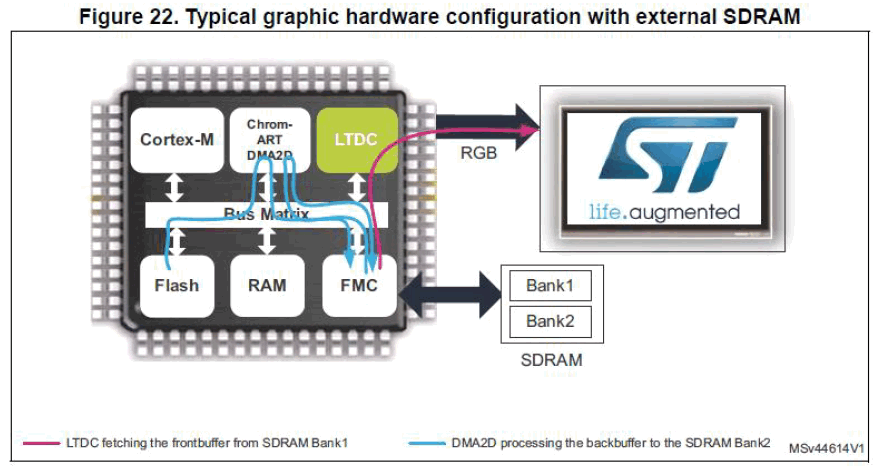
DMA2D is used to reduce CPU usage, and it can perform four basic tasks:
-
Filling rectangular shapes with unique colors.
-
Copying a frame or a rectangular portion of a frame from one memory to another.
-
Converting the pixel format of a frame or a rectangular portion of a frame while transferring it from one memory to another.
-
Blending images of different sizes and pixel formats, storing the resulting image in a result memory.
LTDC and DMA2D/CPU work together. When only one frame buffer is used, there is a risk of displaying the frame buffer calculations on the screen. Multi-buffering techniques (such as double buffering) are typically used to avoid displaying frame buffer calculations on the screen. Even with double buffering, tearing effects may occur due to the asynchrony between LTDC and frame buffer updates (using CPU or DMA2D). One solution to this problem is to use the VSYNC signal to synchronize the workflows of the two masters (LTDC with CPU or DMA2D).
LTDC retrieves graphic data from the buffer (called the front buffer), while DMA2D prepares the next frame in another buffer (called the back buffer). The VSYNC cycle indicates the end of the actual frame display and when the two buffers should be flipped.
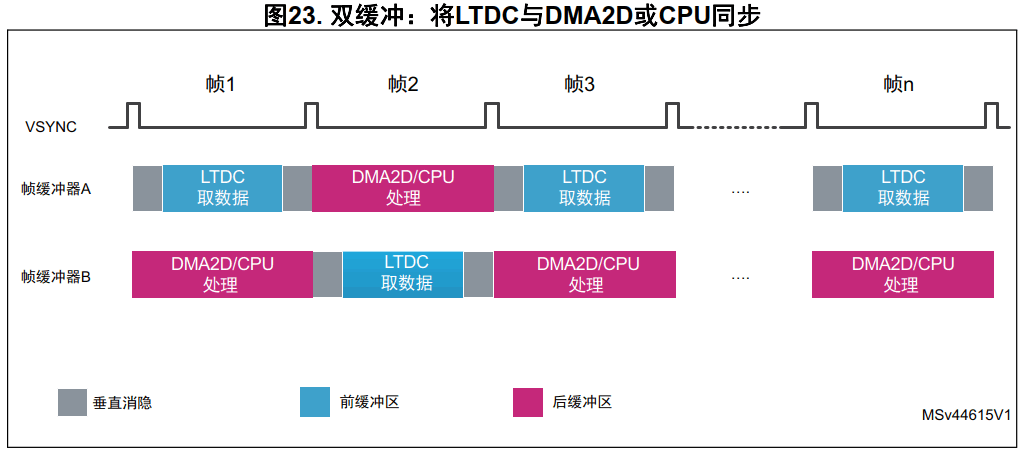
LTDC provides different options to synchronize this workflow:
-
If using the value of the last line of the screen to program the line interrupt, the interrupt handler will flip the frame buffer and start the next frame buffer calculation.
-
Programming the shadow reload register (LTDC_SRCR) for vertical blanking reload to change the LTDC frame buffer address on the VSYNC cycle and polling the VSYNC bit of the LTDC_CDSR register to unblock DMA2D.
Conclusion
The STM32 MCU provides a very flexible display controller that can connect to various displays at a low cost while offering high performance.
Due to the integrated capabilities of its smart architecture, DMA2D is used to accelerate the generation of frame buffer graphic data, while LTDC can automatically retrieve graphic data from the frame buffer and drive it to the display. The hardware support of DMA2D and LTDC allows the graphic display pipeline to operate without any CPU intervention, enabling the CPU to remain in low-power sleep mode more often. This makes it very suitable for low-power and mobile applications such as smartwatches.
References:
STM Document: AN4861, LCD-TFT Display Controller (LTDC) on STM32 MCUs https://www.st.com/resource/en/application_note/an4861-introduction-to-lcdtft-display-controller-ltdc-on-stm32-mcus-stmicroelectronics.pdf