“In today’s world where electronic products are deeply integrated into our lives, low power design is key to extending device battery life and enhancing user experience. As the core control component, the low power modes of MCUs are particularly important. Mainstream MCUs such as the 51 series, STM32, and ESP32 all have adapted modes. Below, we will analyze their low power designs from three aspects: mode comparison, principles, and code implementation..“

Nowadays, various electronic products have become deeply integrated into our lives. The behaviors of devices that we take for granted, such as mobile phones entering standby mode, watches displaying low brightness at night, and sensors waking up for periodic detection, all reflect low power design. These behaviors extend device battery life, reduce charging frequency, and greatly enhance the user experience.
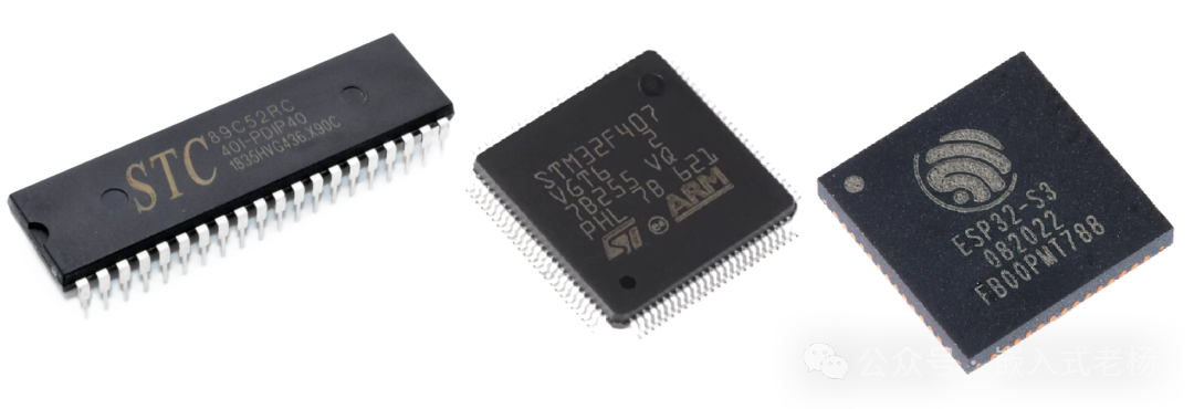
The core control of many electronic devices relies on MCUs. To meet low power demands, mainstream MCUs such as the 51 series, STM32, and ESP32 have developed various low power modes. From simple CPU sleep to deep power-down modes, these modes selectively shut down modules to minimize energy consumption while ensuring functionality, becoming key to long-term operation of devices.
Next, we will introduce the low power design of mainstream MCU products.
01
—
Comparison Table of Low Power Modes of 51, STM32, and ESP32
|
Item |
51 Microcontroller (e.g., STC series) |
STM32 (e.g., Cortex-M series) |
ESP32 (e.g., Xtensa Dual-Core & ULP Coprocessor) |
|
Main Modes |
Idle Mode; Power-Down Mode |
Sleep; Stop; Standby |
Modem-Sleep; Light-Sleep; Deep-Sleep; Hibernate |
|
CPU State |
Idle: CPU stops, peripherals run; Power-Down: CPU and peripherals stop |
Sleep: CPU stops, peripherals run; Stop: CPU and core clock stop; Standby: entire 1.8V domain powered off |
Modem/Light: CPU pauses; Deep/Hibernate: CPU powered off, only RTC/ULP coprocessor runs |
|
Clock State |
Idle: main clock runs; Power-Down: main clock stops |
Sleep: core clock runs; Stop: core clock stops, low-speed clock optional; Standby: all clocks stop |
Modem: CPU clock downscaled or paused; Light: main clock stops, RTC runs; Deep: only RTC slow clock runs |
|
SRAM/Data Retention |
Idle: retained; Power-Down: retained (if voltage sufficient) |
Sleep/Stop: retained; Standby: lost (except backup registers) |
Modem/Light: retained; Deep: partially retained (RTC slow memory); Hibernate: minimal retention |
|
Typical Wake Sources |
Idle: any interrupt; Power-Down: external interrupt, reset pin |
Sleep: any interrupt; Stop: external interrupt, RTC alarm, etc.; Standby: WKUP pin, RTC alarm, NRST pin |
Modem/Light: timer, GPIO, peripheral interrupt; Deep: timer, GPIO, touch sensor; Hibernate: GPIO, timer |
|
Power Consumption Level (Typical) |
Idle: ~2-5mA; Power-Down: <10μA |
Sleep: ~0.1-1mA; Stop: ~5-10μA; Standby: ~0.5-1.5μA |
Modem: ~10-20mA; Light: ~0.4-0.8mA; Deep: ~5-10μA; Hibernate: ~2-5μA |
|
Wake Time |
Idle: very fast; Power-Down: slow (requires clock restart) |
Sleep: very fast; Stop: fast (requires clock stabilization); Standby: slow (equivalent to soft reset) |
Modem/Light: very fast (ms level); Deep: slower (requires RF restart); Hibernate: slow (equivalent to power-on reset) |
|
Wireless Connection Status |
None |
None |
Modem: maintains Wi-Fi connection; Light: disconnected, quick reconnect; Deep/Hibernate: disconnected |
|
Core Features |
Simple modes; Easy configuration; Basic power control |
Fine mode gradient; Rich functionality; Precise power control |
Optimized for wireless applications; Modem sleep can maintain connection; ULP coprocessor can operate in deep sleep |
|
Typical Application Scenarios |
Simple control; Remote controls; Devices requiring quick response after long standby |
Industrial control; sensor acquisition; Wearable devices |
IoT terminals; Devices needing to maintain long connections or periodically report data |
02
—
Principles of Low Power Modes
1. 51 Microcontroller
Idle Mode:
The CPU stops working, but the oscillator, timer, serial port, and other peripherals remain operational, and the contents of internal RAM and special function registers are retained. At this time, the CPU no longer executes instructions, but the interrupt system remains effective, and any interrupt request can wake the CPU to resume normal operation. This mode consumes less power than normal operating mode and is suitable for scenarios where peripherals need to continue running.
Power-Down Mode:
The oscillator stops working, and the CPU and all peripherals stop running, retaining only the data in internal RAM, while the contents of special function registers are lost. An external reset signal or level-triggered external interrupt is required to wake up, and after waking up, the system needs to be reinitialized. This mode has extremely low power consumption and is suitable for long sleep scenarios with strict power requirements and no need for peripherals to run.
2. STM32
Sleep Mode:
The CPU stops running, but the core registers and SRAM contents are retained, and peripherals (such as timers, UART) and clock systems operate normally. It can be awakened by any interrupt or event, and after waking up, it immediately resumes execution, suitable for low power scenarios requiring quick response.
Stop Mode:
The CPU and peripheral clocks are turned off, while the 1.8V domain circuit remains powered, and the SRAM and register contents are retained. There are three levels of Stop: Stop 0 retains more clocks and wakes up the fastest; Stop 2 turns off more circuits and has the lowest power consumption. It requires external interrupts, RTC, etc., to wake up, suitable for scenarios that require a balance between power consumption and wake-up speed.
Standby Mode:
Almost all power is cut off except for the backup domain and wake-up circuits, SRAM and register contents are lost, and power consumption is extremely low. It can only be awakened by a few methods such as WKUP pin, RTC alarm, etc., and after waking up, it is equivalent to a reset start, suitable for low power scenarios with long sleep periods.
3. ESP32
Deep-Sleep Mode:
In deep-sleep mode, the CPU, most RAM, and all digital peripherals are disabled, with only the RTC peripherals, RTC memory, and ULP coprocessor remaining operational. In this mode, the chip’s power consumption is extremely low, typically between 0.15mA and 10µA. Deep-sleep mode can be awakened in the following ways:
Timer Wake: Wake up after a fixed time set by the RTC timer.
External Wake: Wake up by changing the high and low levels of the RTC GPIO pins.
Touch Wake: Wake up through a touch sensor.
Light-Sleep Mode:
In light-sleep mode, the CPU pauses operation, the RTC timer remains active, and the clocks of digital peripherals are turned off. In this mode, power consumption is lower than in deep-sleep mode but higher than in normal operating mode, suitable for scenarios requiring quick wake-up. The power consumption in light-sleep mode is approximately 0.8mA.
Modem-Sleep Mode:
Modem-sleep mode is primarily based on the DTIM mechanism, where the chip automatically enters sleep mode after completing Wi-Fi tasks, turning off the PHY (RF module) to reduce power consumption. In this mode, the chip automatically wakes up during DTIM intervals or when sending data packets.
Hibernate Mode:
Hibernate mode is the lowest power mode of the ESP32, with only RTC memory powered. In this mode, the chip’s power consumption is at its lowest, suitable for ultra-long standby scenarios.
These low power modes enable the ESP32 to effectively reduce energy consumption in various application scenarios, extending the device’s lifespan.
03
—
Implementation Methods for Low Power Modes
1. Code Implementation of Low Power Modes for 51 Microcontroller:
Idle Mode:
Idle mode is triggered by the IDLE bit (bit 0) of the PCON register, and any interrupt can wake it up, continuing to execute the breakpoint code after waking up.
#include <reg51.h>// Enter idle modevoid enter_idle_mode() { PCON |= 0x01; // Set IDLE bit to enter idle mode // Immediately enter idle mode after executing this instruction}// External interrupt 0 service function (used to exit idle mode)void int0_isr(void) interrupt 0 { // Automatically exit idle mode after interrupt trigger, continue executing subsequent code}void main() { EA = 1; // Enable global interrupt EX0 = 1; // Enable external interrupt 0 IT0 = 1; // Set external interrupt 0 to edge-triggered while(1) { // Main loop task... enter_idle_mode(); // Enter idle mode }}Power-Down Mode:
Power-down mode is triggered by the PD bit (bit 1) of the PCON register, and only level-triggered external interrupts or resets can wake it up. After waking up, the program starts from the beginning and needs to reinitialize peripherals.
// Enter power-down modevoid enter_power_down_mode() { PCON |= 0x02; // Set PD bit to enter power-down mode // Enter power-down mode after executing this instruction}void main() { EA = 1; // Enable global interrupt EX0 = 1; // Enable external interrupt 0 IT0 = 0; // Set external interrupt 0 to level-triggered (only level-triggered is effective in power-down mode) while(1) { // Main loop task... enter_power_down_mode(); // Enter power-down mode // After waking up, execute from reset vector, need to reinitialize }}// External interrupt 0 service function (only used for level-triggered wake-up, after waking up the program restarts)void int0_isr(void) interrupt 0 { // Trigger interrupt in power-down mode, system resets and restarts}
2. Code Implementation of Low Power Modes for STM32:
Sleep Mode:
void enter_sleep_mode(void) { // Configure SysTick timer as wake-up source (example) HAL_SYSTICK_Config(HAL_RCC_GetHCLKFreq()/1000); // 1ms interrupt // Enter sleep mode (any interrupt wakes up) HAL_PWR_EnterSLEEPMode(PWR_MAINREGULATOR_ON, PWR_SLEEPENTRY_WFI); // Automatically continue executing from here after waking up}
Stop Mode:
Use HAL_PWR_EnterSTOPMode to enter, and configure external interrupts or RTC as wake-up sources. After waking up, the system clock must be reinitialized.
void enter_stop2_mode(void) { // Enable external interrupt wake-up (e.g., PA0) GPIO_InitTypeDef GPIO_InitStruct = {0}; __HAL_RCC_GPIOA_CLK_ENABLE(); GPIO_InitStruct.Pin = GPIO_PIN_0; GPIO_InitStruct.Mode = GPIO_MODE_IT_RISING; GPIO_InitStruct.Pull = GPIO_NOPULL; HAL_GPIO_Init(GPIOA, &GPIO_InitStruct); HAL_NVIC_EnableIRQ(EXTI0_IRQn); // Enter Stop 2 mode HAL_PWR_EnterSTOPMode(PWR_LOWPOWERREGULATOR_ON, PWR_STOPENTRY_WFI); // After waking up, need to reconfigure system clock SystemClock_Config();}
Standby Mode:
Enter using HAL_PWR_EnterSTANDBYMode, and after waking up, the system resets, requiring reinitialization of all peripherals. Common wake-up sources are RTC alarms or WKUP pins.
void enter_standby_mode(void) { // Configure RTC alarm as wake-up source RTC_HandleTypeDef hrtc; // ... omitted RTC initialization code ... // Enable wake-up pin (PWR_WAKEUP_PIN1) HAL_PWR_EnableWakeUpPin(PWR_WAKEUP_PIN1); // Clear standby flag __HAL_PWR_CLEAR_FLAG(PWR_FLAG_SB); // Enter standby mode HAL_PWR_EnterSTANDBYMode(); // After waking up, execute from reset, will not execute here}// External interrupt service function (used to exit Stop mode)void EXTI0_IRQHandler(void) { HAL_GPIO_EXTI_IRQHandler(GPIO_PIN_0);}// SysTick interrupt service function (used to exit sleep mode)void SysTick_Handler(void) { HAL_IncTick();}
3. Code Implementation of Low Power Modes for ESP32:
Deep-Sleep:
Enter using esp_deep_sleep_start(), and after waking up, the program starts from app_main, requiring reinitialization of peripherals.
void enter_deep_sleep() { // Configure timer wake-up (wake up after 10 seconds) esp_sleep_enable_timer_wakeup(10 * 1000000); // Configure external pin wake-up (GPIO4) esp_sleep_enable_ext0_wakeup(GPIO_NUM_4, 1); // High level wake-up // Configure touch wake-up (touch pad 0) touch_pad_init(); touch_pad_config(TOUCH_PAD_NUM0, 0); esp_sleep_enable_touchpad_wakeup(); printf("Entering deep sleep mode...\n"); esp_deep_sleep_start(); // Enter deep sleep, after waking up starts from app_main}
Light-Sleep:
Enter using esp_light_sleep_start(), and after waking up, continue executing the breakpoint code, maintaining the state.
void enter_light_sleep() { // Configure wake-up sources (similar to deep sleep) esp_sleep_enable_timer_wakeup(5 * 1000000); // Wake up after 5 seconds esp_sleep_enable_ext0_wakeup(GPIO_NUM_4, 1); printf("Entering light sleep mode...\n"); while (1) { esp_light_sleep_start(); // Enter light sleep // Continue executing after waking up printf("Woken up from light sleep\n"); if (esp_sleep_get_wakeup_cause() == ESP_SLEEP_WAKEUP_TIMER) { printf("Wake-up source: timer\n"); break; // Exit loop } }}
Modem-Sleep:
Configure Wi-Fi power-saving mode using esp_wifi_set_ps(), and the system automatically enters during idle time.
void enter_modem_sleep() { // Initialize Wi-Fi wifi_init_config_t cfg = WIFI_INIT_CONFIG_DEFAULT(); esp_wifi_init(&cfg); esp_wifi_set_mode(WIFI_MODE_STA); esp_wifi_start(); // Enable modem sleep esp_wifi_set_ps(WIFI_PS_MAX_MODEM); // Maximum modem sleep printf("Entering modem sleep mode...\n"); // The system will automatically enter modem sleep during Wi-Fi idle vTaskDelay(10000 / portTICK_PERIOD_MS); // Wait for 10 seconds esp_wifi_stop();}
Hibernate Mode:
Configured through deep sleep API, turning off RTC peripheral power, retaining only RTC memory, with the lowest power consumption.
void enter_hibernation() { // Only retain RTC memory power, configure external pin wake-up esp_sleep_pd_config(ESP_PD_DOMAIN_RTC_PERIPH, ESP_PD_OPTION_OFF); esp_sleep_enable_ext0_wakeup(GPIO_NUM_4, 1); printf("Entering hibernation mode...\n"); esp_deep_sleep_start(); // Hibernation mode is implemented through deep sleep configuration}
Previous Articles:
Recommended book suitable for beginners in electronic design (includes electronic version)
Microcontroller AD Acquisition Filtering Algorithm
MCU Memory Mapping Mechanism
MCU Minimum System
Introduction to Common Audio Chips
Common Circuit Simulation Software for Embedded Systems
ESP32-S3 Partition Table