Click the above  “Chuangxue Electronics” to follow us with one click and easily learn electronic knowledge
Single-Key Switch Implementation for Flashlight Power and Function Control Circuit
Most flashlights have a self-locking button at the tail. Pressing the button turns on the flashlight, and if you quickly press this switch, it allows the flashlight to switch between strong light, weak light, flashing, and off modes.
When I first encountered flashlights, I found this feature fascinating. It seemed incredible that a single power switch connected to the battery could achieve button functionality during operation. Later, I disassembled a flashlight to see the internal circuit and finally understood the principle behind it. I believe the designer must have put a lot of thought into making this possible.
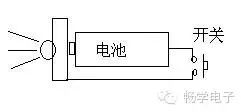
The switch in the image controls the power on and off, and can also switch between strong light, weak light, and flashing functions through quick light presses.
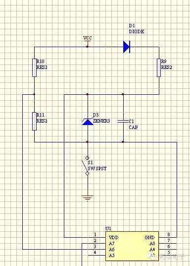
Analysis:
1. S1 is a self-locking switch. When S1 is pressed, the battery’s negative terminal connects to the microcontroller’s GND, allowing the microcontroller to operate normally and control the LED output.
2. A quick light press on S1 disconnects the battery’s negative terminal from the microcontroller’s GND, allowing capacitor C1 to continue supplying power to the microcontroller. As long as C1 has a sufficiently large capacity, it can keep the microcontroller running for a period.
3. When S1 is quickly pressed, since the battery’s negative terminal is disconnected from the microcontroller’s GND, the battery only connects the positive terminal to the entire circuit, without forming any loop. In reality, the battery has no effect, and we can consider R10 and the battery as floating. The microcontroller’s A6 pin connects through R11 to the microcontroller’s GND, reading an external state of 0.
4. When S1 is closed, the battery’s negative terminal connects to the microcontroller’s GND, and the A6 pin reads the state after voltage division from R10 and R11. As long as the resistance of R11 exceeds 3 to 4 times that of R10, the read state will be 1.
5. During steps 3 and 4, the microcontroller can determine that S1 was not quickly pressed based on the state of its A6 pin. If the A6 pin reads state 0, it indicates a quick light press operation, and the flashlight needs to switch functions.
Diode D1 prevents capacitor C1 from supplying reverse current to R10 during quick light presses on S1.
The voltage regulator D3 can be omitted.
Resistor R9 can limit the charging current to the capacitor and can also be omitted.
> > > > > > > > > > > > > > > > > > > > > > > > > > > > > > > > > > > > > > > > > > > > > > > > > > > > > >