NEWS
Click the blue text to follow us
NEWS TODAY
The Brake-by-Wire (BBW) system is an electronic upgrade of the traditional hydraulic braking system, controlling the braking system through electronic signals instead of traditional hydraulic or mechanical methods. This allows for more precise brake force distribution, faster response times, and smarter braking strategies (such as Automatic Emergency Braking (AEB) and Adaptive Cruise Control (ACC)).
The Brake-by-Wire system relies on high-precision sensor data (such as wheel speed, brake pedal position, hydraulic pressure, etc.). In the Brake-by-Wire system, the AK protocol wheel speed sensor is one of the core components for achieving precise braking control.
01 Overview of AK Protocol
Definition of AK Protocol:
The AK protocol is a standard interface for wheel speed sensors (WSS) and electronic control units (ECU) for data signal transmission. The signals generated by the sensor are processed through a signal modulation unit to produce speed signals and data signals. In the Brake-by-Wire system, braking pressure is directly controlled through electronic signals, replacing the traditional hydraulic system.
How to measure AK signals:
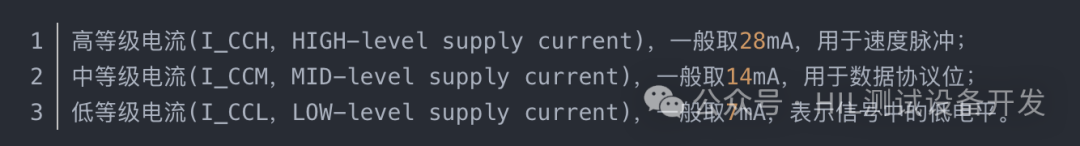
The AK signal transmits data by changing the magnitude of the current, which is divided into three levels. Therefore, it is sufficient to measure the magnitude of the current. Generally, a oscilloscope and a current clamp are needed.
AK Frame Structure:
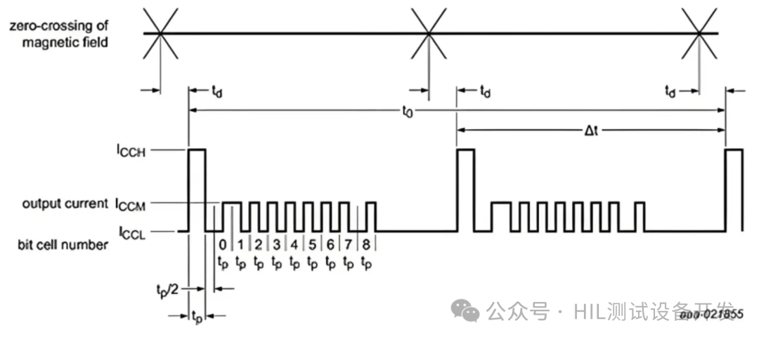
Figure 1 AK Frame Structure
An AK signal frame contains speed pulses and data protocol bits, corresponding to speed signals and data signals.
Each speed pulse represents the sensor passing one tooth, and the wheel speed can be calculated based on the time interval (tooth gap) between two adjacent speed pulses.
The data protocol bits represent additional information, such as rotation direction and field amplitude.
AK Waveform:
Magnetic ring and pulse relationship: 1:2Assuming the number of magnetic poles on the vehicle’s magnetic ring is 48 teeth, then the wheel speed sensor generates a pulse for each magnetic pole (tooth) it passes. The magnetic ring produces a total of 96 pulses in one rotation. One pulse corresponds to Δt in the figure below.
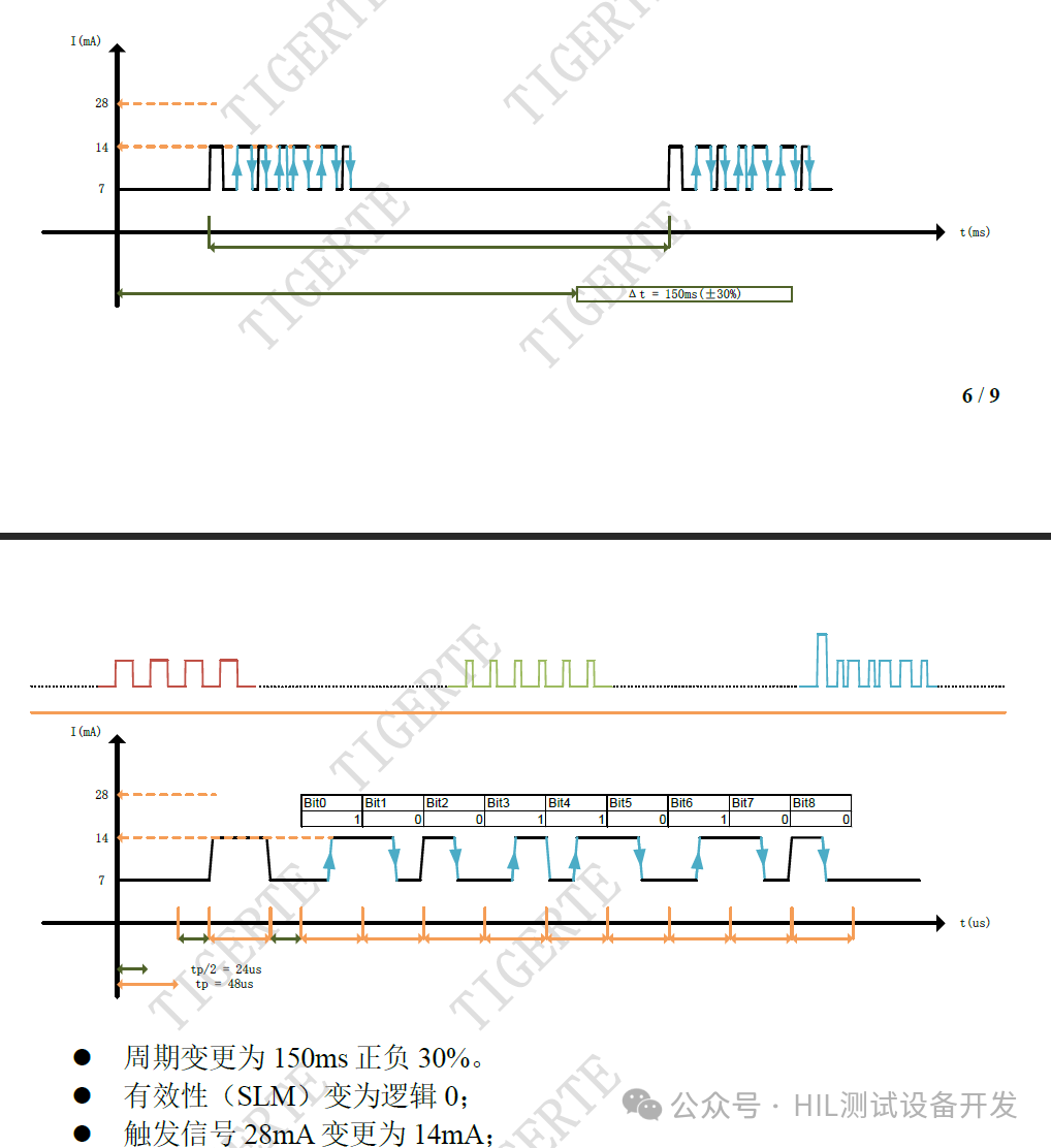
Figure 2 Standstill State
Figure 3 Standstill State
02 Simulation of AK Wheel Speed Sensor
Methods for simulating AK wheel speed sensors:
-
Hardware Simulation
(1) Electromagnetic Sensor Simulation
-
Principle:Simulate the AC voltage signal output by the sensor (e.g., 0.5V~5V sine wave), with frequency proportional to the wheel speed.
-
Implementation:Use a function generator (e.g., Keysight 33522B) to generate a sine wave with adjustable frequency; adjust the signal amplitude and phase using an operational amplifier to match the sensor characteristics.
-
Example Parameters:Wheel speed 100 km/h → Sensor output frequency 1 kHz (assuming gear ratio and sensor parameters are known).
(2) Hall Effect Sensor Simulation
-
Principle: Simulate square wave signals (e.g., 5V TTL level), with a fixed duty cycle (50%), and frequency corresponding to speed.
-
Implementation: Use a microcontroller (STM32/Arduino) or FPGA to output PWM signals; adjust the signal duty cycle using programmable resistors/capacitors (e.g., to simulate sensor fault conditions).
-
Software Simulation
(1) CAN Bus Simulation
-
Tools: PCAN-USB, Vector VN series, SocketCAN (Linux).
-
Implementation Steps:
-
Define the CAN frame format for the AK protocol (e.g., ID, data length, field meanings).
-
Write a program to generate wheel speed data (e.g., Python + python-can library).
-
Send simulated data to the ECU via the CAN bus.
(2) MATLAB/Simulink Modeling
-
Applicable Scenarios: Algorithm development phase, simulating sensor dynamic responses (e.g., tooth gap, noise).
-
Methods:
-
Use Simulink’s Signal Builder to generate speed curves.
-
Use CAN Pack/Unpack modules to encapsulate/decapsulate AK protocol data.
03 Analysis of AK Protocol Wheel Speed Data
In the AK protocol, the signals generated by the wheel speed sensor are processed through a signal conditioning unit to produce speed signals and data signals. Speed pulses reflect the structure of the gears, and the wheel speed can be calculated based on the time interval between two adjacent speed pulses; the data protocol bits represent additional information, such as rotation direction and field amplitude.
Steps for wheel speed data analysis:
-
Signal Acquisition and Conversion:
-
Analog Signal Situation: If the sensor outputs an analog signal (e.g., sine wave voltage signal from an electromagnetic sensor), a signal conditioning circuit is needed to convert it into a voltage signal suitable for processing.
-
Current Signal Conversion: The current signal sent by the AK protocol wheel speed sensor needs to be converted into a voltage signal through a specific circuit.
-
Timestamp Recording
-
Wheel Speed Calculation
-
Data Protocol Bit Analysis
Characteristics of Analysis Under Different Operating Modes:
Depending on the frequency of the input signal, the emitted AK signal will have two states: low-speed operation and high-speed operation.
Low-Speed Operation:
When the input signal frequency is low, and the time since the last detected tooth signal exceeds T_stop (usually 150ms), the signal will be resent, but the speed pulse will be replaced with an artificial speed pulse with a current magnitude of I_CCM.
If no zero-crossing input signal is detected after T_stop, the repetition continues. If no tooth signal is detected within 1 second, or the related hysteresis level does not pass within 250 milliseconds, the system enters low-speed mode, and the mode bit (M) in the protocol data bits changes from 0 to 1.
When resending the signal, if a tooth signal input is detected before a frame of signal is completely sent, the transmission of the repeated signal will be terminated before sending the new speed pulse. Due to the delay t_d, the data unit currently being sent (not a data frame, just a current bit) can be sent completely, and there must be at least a time interval of t_p/2 before sending the new speed pulse, as shown in the figure.
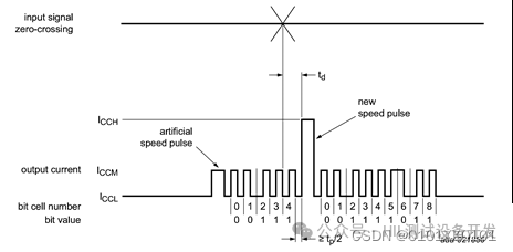
Figure 4 Low-Speed Operation
High-Speed Operation
When the frequency of the input signal is very high, not all of the 9 data units following the speed pulse will necessarily be sent, but the data units being sent can be completed normally, and there must be at least one speed pulse in each frame of data. This operating state is consistent with the termination method of repeated signal transmission in low-speed operation.
04 Application of AK Protocol in Online Brake Control
In the development of online brake systems, verifying the communication logic between the sensor and ECU in advance is key to shortening the cycle.
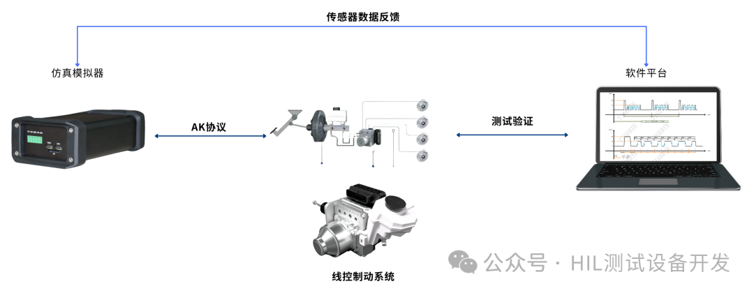
Figure 5 Closed-loop Testing Architecture for AK Wheel Speed Sensor Simulation and Analysis
In the development of online brake systems, the simulation of AK protocol sensors is used for:
-
Wheel Speed Data Simulation Transmission
-
Simulating Real Working Conditions:During development, simulating the AK protocol sensor can generate simulated wheel speed signals to calculate wheel speed.
-
Providing Various Input Scenarios:Different vehicle speeds, steering directions, and sensor fault conditions can be simulated to comprehensively test the performance and reliability of the online brake system.
-
Braking Control Strategy Verification
-
ABS Anti-lock Control Testing:By simulating the AK protocol sensor, the ECU can calculate the angular acceleration and slip rate of each wheel based on the received simulated wheel speed signals, thereby improving the vehicle’s braking stability and handling.
-
ESP Electronic Stability Program Verification:Simulated wheel speed data provided by the AK protocol sensor allows the ESP system to perform accurate calculations and judgments, timely adjusting the braking force of each wheel to restore vehicle stability and ensure driving safety.
-
TCS Traction Control Testing:Simulated wheel speed data transmitted by the AK protocol sensor enables the ECU to detect wheel slip conditions in real-time and maintain stable driving conditions by reducing the driving force of the driven wheels or braking the slipping wheels.
-
System Integration and Debugging
-
Sensor and ECU Matching Tests:By simulating the AK protocol sensor, communication between different models and specifications of sensors and the ECU can be simulated to check compatibility and data transmission accuracy.
-
Control Algorithm Verification:Simulating the AK protocol sensor can provide various input data to verify the correctness and effectiveness of control algorithms, optimizing and adjusting control algorithms to improve system performance.
-
Fault Diagnosis and Safety Mechanism Testing
-
Fault Diagnosis Testing:Simulated sensors can generate various fault signals, and by simulating and analyzing these fault signals, the ECU’s fault diagnosis capability can be tested.
-
Safety Mechanism Verification:By simulating the AK protocol sensor, these safety mechanisms can be tested to ensure the safety and reliability of critical control commands in the braking system.
05 Conclusion
The AK wheel speed sensor can effectively assist in the development of Brake-by-Wire systems, and its simulation and analysis are core aspects of Brake-by-Wire system development, involving:
-
Signal Simulation: Hardware (function generator/microcontroller) or software generates wheel speed data.
-
Data Analysis: Extracting information such as speed and direction based on the protocol frame structure.
-
Testing and Verification: Using hardware/software tools to cover normal/fault scenarios to ensure system reliability.
Note: Some materials are sourced from the internet.
END

Scan the code to follow us